СИСТЕМА ECD (для моделей без контроллера свечей накаливания) Starter Signal Circuit
DESCRIPTION
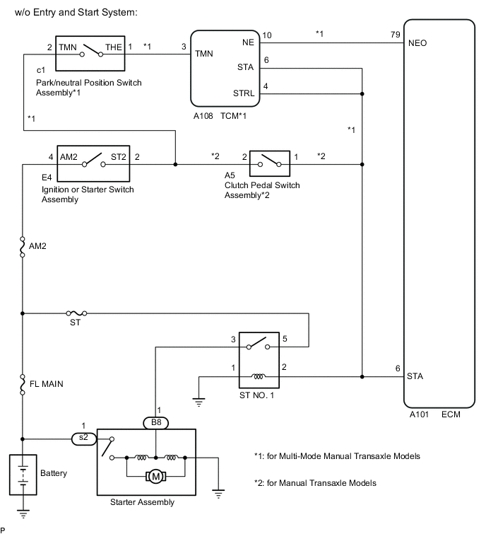
w/o Entry and Start System:
While the engine is being cranked, current flows from terminal ST2 of the ignition or starter switch assembly to the park/neutral position switch assembly*1 or clutch pedal switch assembly*2 and also flows to terminal STA of the ECM (STA Signal).
*1: for Multi-mode manual transaxle models
*2: for Manual transaxle models
WIRING DIAGRAM
CAUTION / NOTICE / HINT
Note
-
When replacing the ECM, perform ECM Initialization and Registration.
-
Inspect the fuses for circuits related to this system before performing the following procedure.
Tech Tips
When the ECM must be replaced, before replacing the ECM, perform the "Learning Values Save" function using the GTS. Then after installing a new ECM, perform all of the initialization and registration procedures for the "Learning Values Write" function by following the instructions shown on the GTS display.
PROCEDURE
-
CHECK WHETHER ENGINE CAN BE CRANKED
-
Check if the engine can be cranked.
Result Result Proceed to Engine cannot be cranked A Engine can be cranked B
B 
READ VALUE USING GTS (STARTER SIGNAL) Click here
A 
-
-
INSPECT RELAY (ST NO. 1 RELAY)
-
Inspect the ST NO. 1 relay.
Result Proceed to OK NG
NG 
REPLACE RELAY (ST NO. 1 RELAY)
OK
-
-
READ VALUE USING GTS (STARTER SIGNAL)
-
Connect the GTS to the DLC3.
-
Turn the ignition switch to ON.
-
Turn the GTS on.
-
Enter the following menus: Powertrain / Engine and ECT / Data List / Starter Signal.
Powertrain > Engine and ECT > Data ListTester Display Starter Signal -
Check the value displayed on the GTS when the ignition switch is turned to the ON and START positions.
OK Ignition Switch Position Starter Signal ON OFF START ON Result Result Proceed to OK A NG (Manual transaxle models) B NG (Multi-mode manual transaxle models) C
B
CHECK TERMINAL VOLTAGE (POWER SOURCE OF CLUTCH PEDAL SWITCH ASSEMBLY) Click here
C
CHECK TERMINAL VOLTAGE (POWER SOURCE OF PARK/NEUTRAL POSITION SWITCH ASSEMBLY) Click here
A
-
-
CHECK TERMINAL VOLTAGE (POWER SOURCE OF ST NO. 1 RELAY)
-
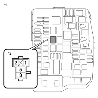
*1 Engine Room Relay Block and Junction Block Assembly *2 ST NO. 1 Relay Remove the ST NO. 1 relay assembly from the engine room relay block and junction block assembly.
-
Measure the voltage according to the value(s) in the table below.
Standard Voltage Tester Connection Condition Specified Condition ST NO. 1 relay terminal 2 - Body ground Cranking 11 to 14 V ST NO. 1 relay terminal 5 - Body ground Always 11 to 14 V Result Result Proceed to Normal A Abnormal (Starter relay terminal 2) B Abnormal (Starter relay terminal 5) C
B
REPAIR OR REPLACE HARNESS OR CONNECTOR (ECM - ST NO. 1 RELAY)
C
REPAIR OR REPLACE HARNESS OR CONNECTOR (BATTERY - ST NO. 1 RELAY)
A
-
-
CHECK HARNESS AND CONNECTOR (ST NO. 1 RELAY - BODY GROUND)
-
Remove the ST NO. 1 relay assembly from the engine room relay block and junction block assembly.
-
Measure the resistance according to the value(s) in the table below.
Standard Resistance Tester Connection Condition Specified Condition ST NO. 1 relay terminal 1 - Body ground Always Below 1 Ω Result Proceed to OK NG
NG
REPAIR OR REPLACE HARNESS OR CONNECTOR
OK
-
-
CHECK HARNESS AND CONNECTOR (STARTER ASSEMBLY - ST NO. 1 RELAY)
-
Remove the ST NO. 1 relay assembly from the engine room relay block and junction block assembly.
-
Disconnect the starter assembly connector.
-
Measure the resistance according to the value(s) in the table below.
Standard Resistance Tester Connection Condition Specified Condition B8-1 - ST NO. 1 relay terminal 3 Always Below 1 Ω B8-1 or ST NO. 1 relay terminal 3 - Body ground Always 10 kΩ or higher Result Proceed to OK NG
OK
PROCEED TO NEXT SUSPECTED AREA SHOWN IN PROBLEM SYMPTOMS TABLE Click here
NG
REPAIR OR REPLACE HARNESS OR CONNECTOR
-
-
CHECK TERMINAL VOLTAGE (POWER SOURCE OF CLUTCH PEDAL SWITCH ASSEMBLY)
-
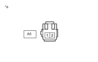
*a Front view of wire harness connector
(to Clutch Pedal Switch Assembly)
Disconnect the clutch pedal switch connector.
-
Measure the voltage according to the value(s) in the table below.
Standard Voltage Tester Connection Condition Specified Condition A5-2 - Body ground Cranking 11 to 14 V Result Proceed to OK NG
NG
GO TO STEP 14 Click here
OK
-
-
INSPECT CLUTCH PEDAL SWITCH ASSEMBLY
-
Inspect the clutch pedal switch assembly.
Result Proceed to OK NG
OK
REPAIR OR REPLACE HARNESS OR CONNECTOR (ECM - CLUTCH PEDAL SWITCH ASSEMBLY - ST NO. 1 RELAY)
NG
REPLACE CLUTCH PEDAL SWITCH ASSEMBLY Click here
-
-
CHECK TERMINAL VOLTAGE (POWER SOURCE OF PARK/NEUTRAL POSITION SWITCH ASSEMBLY)
-
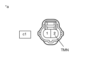
*a Front view of wire harness connector
(to Park/Neutral Position Switch Assembly)
Disconnect the park/neutral position switch assembly connector.
-
Measure the voltage according to the value(s) in the table below.
Standard Voltage Tester Connection Condition Specified Condition c1-2 (TMN) - Body ground Cranking 11 to 14 V Result Proceed to OK NG
NG
CHECK TERMINAL VOLTAGE (POWER SOURCE OF IGNITION OR STARTER SWITCH ASSEMBLY) Click here
OK
-
-
INSPECT PARK/NEUTRAL POSITION SWITCH ASSEMBLY
-
Inspect the park/neutral position switch assembly.
Result Proceed to OK NG
NG
REPLACE PARK/NEUTRAL POSITION SWITCH ASSEMBLY Click here
OK
-
-
CHECK TERMINAL VOLTAGE (TCM)
-
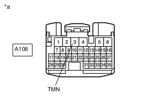
*a Front view of wire harness connector
(to TCM)
Disconnect the TCM connector.
-
Measure the voltage according to the value(s) in the table below.
Standard Voltage Tester Connection Condition Specified Condition A108-3 (TMN) - Body ground Cranking 11 to 14 V Result Proceed to OK NG
NG
REPAIR OR REPLACE HARNESS OR CONNECTOR (PARK/NEUTRAL POSITION SWITCH ASSEMBLY - TCM)
OK
-
-
CHECK HARNESS AND CONNECTOR (ECM - TCM - ST NO. 1 RELAY)
-
Disconnect the ECM connector.
-
Disconnect the TCM connector.
-
Remove the ST NO. 1 relay assembly from the engine room relay block and junction block assembly.
-
Measure the resistance according to the value(s) in the table below.
Standard Resistance Tester Connection Condition Specified Condition A108-6 (STA) - ST NO. 1 relay terminal 2 Always Below 1 Ω A108-4 (STRL) - ST NO. 1 relay terminal 2 Always Below 1 Ω A101-6 (STA) - ST NO. 1 relay terminal 2 Always Below 1 Ω A108-6 (STA) or A108-4 (STRL) or A101-6 (STA) or ST NO. 1 relay terminal 2 - Body ground Always 10 kΩ or higher Result Proceed to OK NG
OK
CHECK MULTI-MODE MANUAL TRANSAXLE SYSTEM Click here
NG
REPAIR OR REPLACE HARNESS OR CONNECTOR
-
-
READ VALUE USING GTS (STARTER SIGNAL)
-
Connect the GTS to the DLC3.
-
Turn the ignition switch to ON.
-
Turn the GTS on.
-
Enter the following menus: Powertrain / Engine and ECT / Data List / Starter Signal.
Powertrain > Engine and ECT > Data ListTester Display Starter Signal -
Check the value displayed on the GTS when the ignition switch is turned to the ON and START positions.
OK Ignition Switch Position Starter Signal ON OFF START ON Result Proceed to OK NG
OK
PROCEED TO NEXT SUSPECTED AREA SHOWN IN PROBLEM SYMPTOMS TABLE Click here
NG
CHECK HARNESS AND CONNECTOR (ECM - ST NO. 1 RELAY) Click here
-
-
CHECK TERMINAL VOLTAGE (POWER SOURCE OF IGNITION OR STARTER SWITCH ASSEMBLY)
-
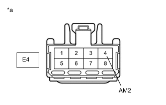
*a Front view of wire harness connector
(to Ignition or Starter Switch Assembly)
Disconnect the ignition or starter switch assembly connector.
-
Measure the voltage according to the value(s) in the table below.
Standard Voltage Tester Connection Condition Specified Condition E4-4 (AM2) - Body ground Always 11 to 14 V Result Proceed to OK NG
NG
REPAIR OR REPLACE HARNESS OR CONNECTOR (BATTERY - IGNITION OR STARTER SWITCH ASSEMBLY)
OK
-
-
INSPECT IGNITION OR STARTER SWITCH ASSEMBLY
-
Inspect the ignition or starter switch assembly.
Result Result Proceed to NG A OK (Manual transaxle models) B OK (Multi-mode manual transaxle models) C
A
REPLACE IGNITION OR STARTER SWITCH ASSEMBLY Click here
B
REPAIR OR REPLACE HARNESS OR CONNECTOR (IGNITION OR STARTER SWITCH ASSEMBLY - CLUTCH PEDAL SWITCH ASSEMBLY)
C
REPAIR OR REPLACE HARNESS OR CONNECTOR (IGNITION OR STARTER SWITCH ASSEMBLY - PARK/NEUTRAL POSITION SWITCH ASSEMBLY)
-
-
CHECK HARNESS AND CONNECTOR (ECM - ST NO. 1 RELAY)
-
Disconnect the ECM connector.
-
Disconnect the transmission control ECU assembly connector (for Multi-Mode manual transaxle models).
-
Disconnect the clutch pedal switch assembly connector (for manual transaxle models).
-
Remove the ST NO. 1 relay assembly from the engine room relay block and junction block assembly.
-
Measure the resistance according to the value(s) in the table below.
Standard Resistance Tester Connection Condition Specified Condition A101-6 (STA) - ST NO. 1 relay terminal 2 Always Below 1 Ω Result Proceed to OK NG
OK
REPLACE ECM Click here
NG
REPAIR OR REPLACE HARNESS OR CONNECTOR
-