ROOF HEADLINING(for Hatchback) INSTALLATION
PROCEDURE
-
INSTALL ROOF HEADLINING ASSEMBLY (for Standard Roof)
-
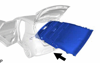
Pull the roof headlining assembly back into the vehicle through the back door.
Note
Do not damage the roof headlining assembly or vehicle interior.
-
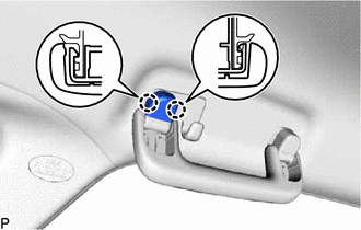
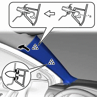
Engage the 2 guides.
-
Engage the 2 claws.
Tech Tips
Use the same procedure for the RH side and LH side.
-
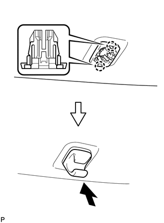
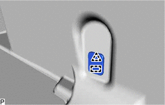
Push in the visor holder as shown in the illustration.
Tech Tips
Use the same procedure for the RH side and LH side.
-
w/o Vanity Light:
-
Install the roof headlining assembly with the 3 clips.
-
-
w/ Vanity Light:
-
Install the roof headlining assembly with the 5 clips.
-
-
for LHD Front Pillar LH Side:
-
Engage the 6 clamps.
-
Connect the connector.
-
-
for RHD Front Pillar LH Side:
-
Engage the 5 clamps.
-
Connect the connector.
-
-
for Front Pillar RH Side:
-
Engage the 3 clamps.
-
Connect the connector.
-
-
for Rear Pillar RH Side:
-
Connect the connector.
-
Engage the guide.
-
Connect the connector bracket with the bolt.
- Torque:
- 7.0 N*m { 71 kgf*cm, 62 in.*lbf }
-
-
w/ EC Mirror:
-
Connect the connector.
-
-
w/ Rain Sensor:
-
Connect the connector.
-
-
-
INSTALL ROOF HEADLINING ASSEMBLY (for Glass Roof)
-
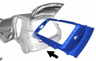
Pull the roof headlining assembly back into the vehicle through the back door.
Note
Do not damage the roof headlining assembly or vehicle interior.
-
Engage the 2 guides (A).
-
Engage the guide (B).
-
Engage the 2 claws.
Tech Tips
Use the same procedure for the RH side and LH side.
-
Push in the visor holder as shown in the illustration.
Tech Tips
Use the same procedure for the RH side and LH side.
-
Engage the 14 fasteners.
Tech Tips
Engage the fasteners from the front side of the roof headlining assembly.
-
Install the roof headlining assembly with the 3 clips.
-
for LHD Front Pillar LH Side:
-
Engage the 6 clamps.
-
Connect the connector.
-
-
for RHD Front Pillar LH Side:
-
Engage the 5 clamps.
-
Connect the connector.
-
-
for Front Pillar RH Side:
-
Engage the 3 clamps.
-
Connect the connector.
-
-
for Rear pillar LH Side:
-
Connect the connector.
-
-
for Rear Pillar RH Side:
-
Connect the connector.
-
Engage the guide.
-
Connect the connector bracket with the bolt.
- Torque:
- 7.0 N*m { 71 kgf*cm, 62 in.*lbf }
-
-
w/ EC Mirror:
-
Connect the connector.
-
-
w/ Rain Sensor:
-
Connect the connector.
-
-
-
INSTALL VISOR ASSEMBLY LH
-
for "TORX" Screw:
-
Using a T25 "TORX" socket wrench, install the visor assembly LH with the 2 screws.
-
-
except "TORX" Screw:
-
Install the visor assembly LH with the 2 screws.
-
-
-
INSTALL VISOR ASSEMBLY RH
Tech Tips
Use the same procedure as for the LH side.
-
INSTALL ASSIST GRIP ASSEMBLY
Tech Tips
Use the same procedure to install all assist grip assemblies.
-
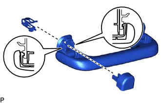
Install the clip and assist grip cover LH to the assist grip as shown in the illustration.
-
Install the clip and assist grip cover RH.
Tech Tips
Use the same procedure as for the LH side.
-
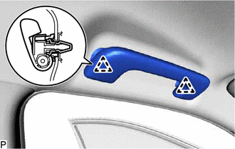
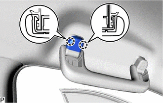
Engage the 2 clips to install the assist grip assembly.
-
Engage the 2 claws to install the assist grip cover LH as shown in the illustration.
-
Install the assist grip cover RH.
Tech Tips
Use the same procedure as for the LH side.
-
-
INSTALL REAR ASSIST GRIP ASSEMBLY LH
-
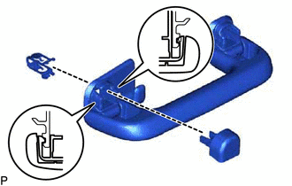
Install the clip and assist grip cover LH to the assist grip as shown in the illustration.
-
Install the clip and assist grip cover RH.
Tech Tips
Use the same procedure as for the LH side.
-
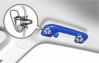
Engage the 2 clips to install the rear assist grip assembly LH.
-
Engage the 2 claws to install the assist grip cover LH as shown in the illustration.
-
Install the assist grip cover RH.
Tech Tips
Use the same procedure as for the LH side.
-
-
INSTALL REAR ASSIST GRIP ASSEMBLY RH
Tech Tips
Use the same procedure as for the LH side.
-
INSTALL NO. 1 ROOM LIGHT ASSEMBLY (for Slide Switch Type)
-
INSTALL MAP LIGHT ASSEMBLY
-
INSTALL RAIN SENSOR COVER (w/ Rain Sensor)
-
INSTALL INNER REAR VIEW MIRROR STAY HOLDER COVER (w/ EC Mirror)
-
INSTALL UPPER INSTRUMENT PANEL
-
INSTALL ROOF SIDE INNER GARNISH ASSEMBLY LH
-
Install a new clip (A) to the roof side inner garnish assembly LH.
-
Engage the 6 clips to install the roof side inner garnish assembly LH.
-
-
INSTALL DECK TRIM SIDE PANEL ASSEMBLY LH
-
Connect the connector.
-
Engage the 3 claws, 4 clips and 2 guides to install the deck trim side panel assembly LH.
-
w/ Deck Board:
-
Engage the 2 clips.
-
Install the deck side trim box LH with the clip.
-
-
for Clip Type:
-
Engage the clip and guide to install the deck trim service hole cover.
-
-
for Hook Type:
-
Engage the guide.
-
Install the luggage hold belt striker assembly with the bolt.
-
-
-
INSTALL LOWER DECK TRIM SIDE BOARD LH (w/ Deck Board)
-
Engage the guide to install the lower deck trim side board LH.
-
-
INSTALL NO. 2 DECK SIDE TRIM HOOK (for LH Side)
-
Engage the pin.
-
Install the No. 2 deck side trim hook with the screw.
-
-
INSTALL REAR SEAT SIDE GARNISH LH
-
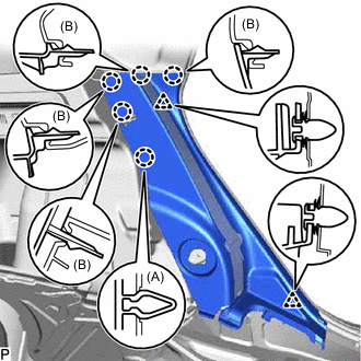
Engage the claw (A).
-
Engage the 4 claws (B) and 2 clips to install the rear seat side garnish LH.
-
-
INSTALL REAR SEATBACK HINGE SUB-ASSEMBLY LH
-
Install the rear seatback hinge sub-assembly LH with the bolt.
- Torque:
- 18 N*m { 184 kgf*cm, 13 ft.*lbf }
-
-
INSTALL ROOF SIDE INNER GARNISH ASSEMBLY RH
Tech Tips
Use the same procedure as for the LH side.
-
INSTALL DECK TRIM SIDE PANEL ASSEMBLY RH
Tech Tips
Use the same procedure as for the LH side.
-
INSTALL NO. 2 DECK SIDE TRIM HOOK (for RH Side)
Tech Tips
Use the same procedure as for the LH side.
-
INSTALL REAR SEAT SIDE GARNISH RH
Tech Tips
Use the same procedure as for the LH side.
-
INSTALL REAR SEATBACK HINGE SUB-ASSEMBLY RH
Tech Tips
Use the same procedure as for the LH side.
-
INSTALL CENTER PILLAR GARNISH ASSEMBLY LH
-
Install a new clip to the center pillar garnish assembly LH.
-
Pass the floor anchor of the front seat outer belt assembly LH through the center pillar garnish assembly LH.
-
Engage the clip.
-
Install the center pillar garnish assembly LH with the 2 screws.
-
-
INSTALL CENTER PILLAR LOWER GARNISH LH
-
Engage the 2 claws, 3 clips and 2 guides to install the center pillar lower garnish LH.
-
-
CONNECT FRONT SEAT OUTER BELT ASSEMBLY LH
-
INSTALL LAP BELT OUTER ANCHOR COVER (for LH Side)
-
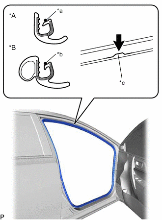
INSTALL REAR DOOR OPENING TRIM WEATHERSTRIP LH
-
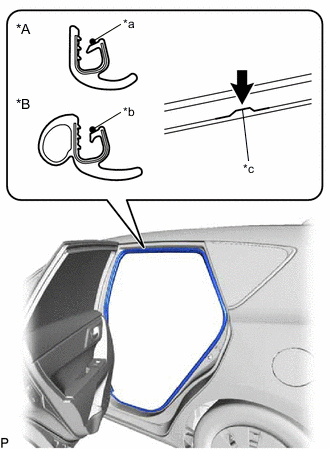
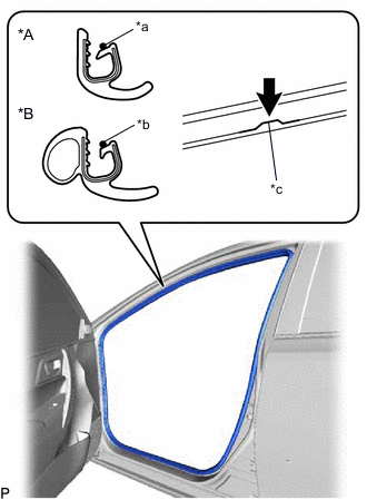
*A for Type A *B for Type B *a Alignment Mark (Yellow) *b Alignment Mark (Orange) *c Flange Position for Type A:
-
Align the alignment mark (yellow) on the weatherstrip with the flange on the vehicle body indicated by the arrow in the illustration, and install the rear door opening trim weatherstrip LH.
Note
After installation, check that the corners fit correctly.
-
-
for Type B:
-
Align the alignment mark (orange) on the weatherstrip with the flange on the vehicle body indicated by the arrow in the illustration, and install the rear door opening trim weatherstrip LH.
Note
After installation, check that the corners fit correctly.
-
-
-
INSTALL REAR UNDER SIDE COVER LH
-
Engage the 2 claws and 2 clips.
-
Install the rear under side cover LH with the 2 clips.
-
-
INSTALL REAR DOOR SCUFF PLATE LH
-
Engage the 8 claws to install the rear door scuff plate LH.
-
-
INSTALL FRONT PILLAR GARNISH LH
-
Remove the protective cover.
-
Make sure that the front pillar garnish clip is not damaged.
Note
If the front pillar garnish clip is damaged, replace the front pillar garnish clip with a new one.
-
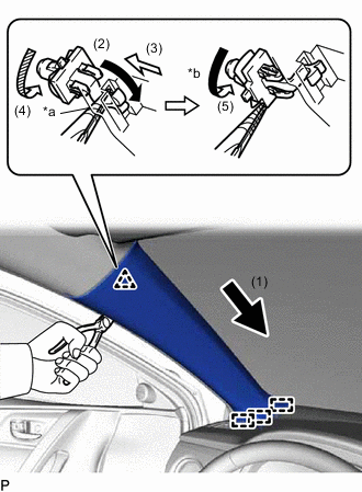
*a Protective tape *b 90° Push the front pillar garnish LH in the direction indicated by the arrow (1) shown in the illustration to engage the 3 guides.
-
Using needle-nose pliers with the tips wrapped with protective tape, bend the end of the front pillar garnish clip in the direction indicated by the arrow (2) shown in the illustration.
-
Push the front pillar garnish LH in the direction indicated by the arrow (3) shown in the illustration and to engage to the front pillar garnish clip.
-
Using needle-nose pliers with the tips wrapped with protective tape, rotate the front pillar garnish clip in the direction indicated by the arrow (4) shown in the illustration.
Tech Tips
Rotate the front pillar garnish clip so that the longer end of the front pillar garnish clip is positioned at the bottom.
-
Using needle-nose pliers with the tips wrapped with protective tape, push the front pillar garnish clip in the direction indicated by the arrow (5) and rotate it to the position shown in the illustration.
Tech Tips
Make sure that the front pillar garnish clip is positioned as shown in the illustration. Failing to do so may cause a gap between the front pillar garnish LH and roof headlining assembly.
-
*a Front Pillar Garnish Clip Engage the clip and front pillar garnish clip to install the front pillar garnish LH.
Note
If there is a gap between the front pillar garnish LH and roof headlining assembly, the front pillar garnish clip is not installed correctly. While lightly pressing the front pillar garnish LH as shown in the illustration, push it towards the front pillar garnish clip side.
Tech Tips
Make sure that the curtain shield airbag assembly LH is not pinched.
-
-
INSTALL FRONT DOOR OPENING TRIM WEATHERSTRIP LH
-
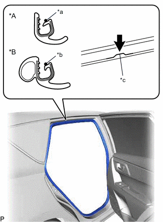
*A for Type A *B for Type B *a Alignment Mark (Pink) *b Alignment Mark (Purple) *c Flange Position for Type A:
-
Align the alignment mark (pink) on the weatherstrip with the flange on the vehicle body indicated by the arrow in the illustration, and install the front door opening trim weatherstrip LH.
Note
After installation, check that the corners fit correctly.
-
-
for Type B:
-
Align the alignment mark (purple) on the weatherstrip with the flange on the vehicle body indicated by the arrow in the illustration, and install the front door opening trim weatherstrip LH.
Note
After installation, check that the corners fit correctly.
-
-
-
INSTALL COWL SIDE TRIM BOARD LH
-
Engage the claw and clip.
-
Install the cowl side trim board LH with the clip.
-
-
INSTALL FRONT DOOR SCUFF PLATE LH
-
Engage the 10 claws to install the front door scuff plate LH.
-
-
INSTALL CENTER PILLAR GARNISH ASSEMBLY RH
Tech Tips
Use the same procedure as for the LH side.
-
INSTALL CENTER PILLAR LOWER GARNISH RH
Tech Tips
Use the same procedure as for the LH side.
-
CONNECT FRONT SEAT OUTER BELT ASSEMBLY RH
Tech Tips
Use the same procedure as for the LH side.
-
INSTALL LAP BELT OUTER ANCHOR COVER (for RH Side)
Tech Tips
Use the same procedure as for the LH side.
-
INSTALL REAR DOOR OPENING TRIM WEATHERSTRIP RH
-
*A for Type A *B for Type B *a Alignment Mark (White) *b Alignment Mark (Yellow) *c Flange Position for Type A:
-
Align the alignment mark (white) on the weatherstrip with the flange on the vehicle body indicated by the arrow in the illustration, and install the rear door opening trim weatherstrip RH.
Note
After installation, check that the corners fit correctly.
-
-
for Type B:
-
Align the alignment mark (yellow) on the weatherstrip with the flange on the vehicle body indicated by the arrow in the illustration, and install the rear door opening trim weatherstrip RH.
Note
After installation, check that the corners fit correctly.
-
-
-
INSTALL REAR UNDER SIDE COVER RH
Tech Tips
Use the same procedure as for the LH side.
-
INSTALL REAR DOOR SCUFF PLATE RH
Tech Tips
Use the same procedure as for the LH side.
-
INSTALL FRONT PILLAR GARNISH RH
Tech Tips
Use the same procedure as for the LH side.
-
INSTALL FRONT DOOR OPENING TRIM WEATHERSTRIP RH
-
*A for Type A *B for Type B *a Alignment Mark (Blue) *b Alignment Mark (Red) *c Flange Position for Type A:
-
Align the alignment mark (blue) on the weatherstrip with the flange on the vehicle body indicated by the arrow in the illustration, and install the front door opening trim weatherstrip RH.
Note
After installation, check that the corners fit correctly.
-
-
for Type B:
-
Align the alignment mark (red) on the weatherstrip with the flange on the vehicle body indicated by the arrow in the illustration, and install the front door opening trim weatherstrip RH.
Note
After installation, check that the corners fit correctly.
-
-
-
INSTALL COWL SIDE TRIM BOARD RH
Tech Tips
Use the same procedure as for the LH side.
-
INSTALL FRONT DOOR SCUFF PLATE RH
Tech Tips
Use the same procedure as for the LH side.
-
INSTALL REAR SEAT ASSEMBLY
-
INSTALL REAR DECK TRIM COVER
-
w/o Deck Board:
-
Engage the 4 claws, 4 clips and 2 guides to install the rear deck trim cover.
-
-
w/ Deck Board:
-
Engage the 4 claws, 4 clips and 4 guides to install the rear deck trim cover.
-
-
for Clip Type:
-
Install the 2 clips.
-
-
for Hook Type:
-
Engage the 2 guides.
-
Install the 2 luggage hold belt striker assemblies with the 2 bolts.
-
-
-
INSTALL PACKAGE TRAY TRIM PANEL ASSEMBLY (w/ Package Tray Trim)
-
Install the package tray trim panel assembly.
-
-
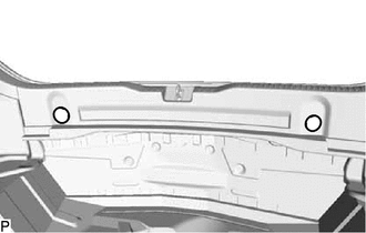
INSTALL DECK FLOOR BOX RH (w/ Deck Floor Box)
-
Install the deck floor box RH with the 2 nuts.
-
-
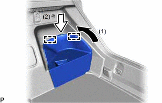
INSTALL DECK FLOOR BOX LH (w/ Deck Floor Box)
-
w/o Woofer:
-
Engage the claw.
-
Install the deck floor box LH with the 2 nuts.
-
-
w/ Woofer:
-
Engage the claw.
-
Install the deck floor box LH with the nut.
-
-
-
INSTALL REAR DECK FLOOR BOX (w/ Deck Floor Box)
-
Engage the guide to install the rear deck floor box.
-
-
INSTALL REAR FLOOR MAT ASSEMBLY
-
Install the rear floor mat assembly.
-
-
INSTALL DECK BOARD ASSEMBLY (w/ Deck Board)
-
Install the deck board assembly.
-
-
INSTALL BATTERY BOX COVER
-
Engage the 2 guides as indicated by the arrows, in the order shown in the illustration to install the battery box cover.
-