ROOF HEADLINING(for Hatchback) REASSEMBLY
PROCEDURE
-
INSTALL NO. 1 ROOF WIRE (for Standard Roof)
-
Align the positioning tape on the front part of the No. 1 roof wire with the front tab of the roof headlining.
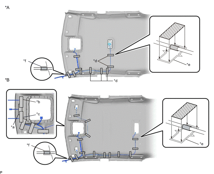
*A w/o Vanity Light *B w/ Vanity Light *a w/ EC Mirror *b for LHD with Rain Sensor *c for RHD with Rain Sensor *d w/ No. 1 Room Light *e Marking *f Front Tab 
Positioning Tape 
Adhesive Tape -
Align the No. 1 roof wire positioning tape with the markings on the roof headlining.
-
Install the No. 1 roof wire onto the roof headlining with adhesive tape.
Note
-
Apply the tape securely in place.
-
Do not touch the adhesive surface when applying the tape to prevent adhesion failure.
-
-
-
INSTALL NO. 1 ROOF WIRE (for Glass Roof)
-
Align the positioning tape on the front part of the No. 1 roof wire with the front tab of the roof headlining.
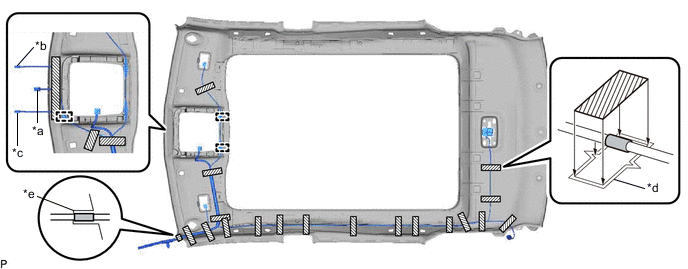
*a w/ EC Mirror *b for LHD with Rain Sensor *c for RHD with Rain Sensor *d Marking *e Front Tab - - Positioning Tape Adhesive Tape -
Engage each clamp.
-
Align the No. 1 roof wire positioning tape with the markings on the roof headlining.
-
Install the No. 1 roof wire onto the roof headlining with adhesive tape.
Note
-
Apply the tape securely in place.
-
Do not touch the adhesive surface when applying the tape to prevent adhesion failure.
-
-
-
INSTALL NO. 2 ROOF HEADLINING PAD (for Standard Roof)
-
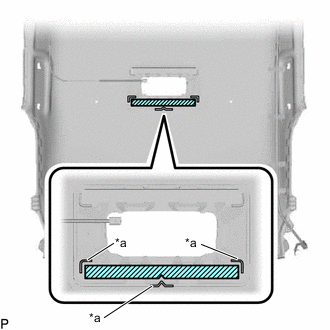
*a Marking w/ Vanity Light:
-
Remove the release paper from a new No. 2 roof headlining pad.
Tech Tips
After removing the release paper, keep the exposed adhesive free from foreign matter.
-
Align the markings on the roof headlining with the No. 2 roof headlining pad and install the pad as shown in the illustration.
-
-
-
INSTALL ROOF HEADLINING PAD (for Standard Roof)
-
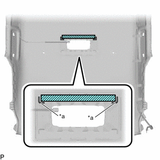
*a Marking w/ Vanity Light:
-
Remove the release paper from a new roof headlining pad.
Tech Tips
After removing the release paper, keep the exposed adhesive free from foreign matter.
-
Align the markings on the roof headlining with the roof headlining pad and install the pad as shown in the illustration.
-
-
-
INSTALL NO. 5 ROOF SILENCER PAD (for Standard Roof)
-
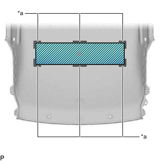
*a Marking w/ Silencer Pad:
-
Align the markings on the roof headlining with the No. 5 roof silencer pad and install the pad using hot-melt glue as shown in the illustration.
-
-
-
INSTALL NO. 1 ROOF SILENCER PAD (for Standard Roof)
-
w/ Silencer Pad:
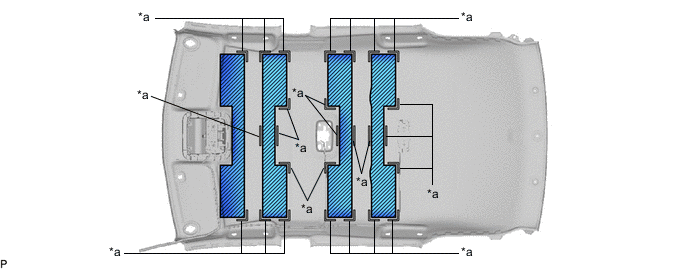
*a Marking - -
-
Align the markings on the roof headlining with the 4 No. 1 roof silencer pads and install the pads using hot-melt glue as shown in the illustration.
-
-
-
INSTALL NO. 3 ROOF SILENCER PAD (for Standard Roof)
-
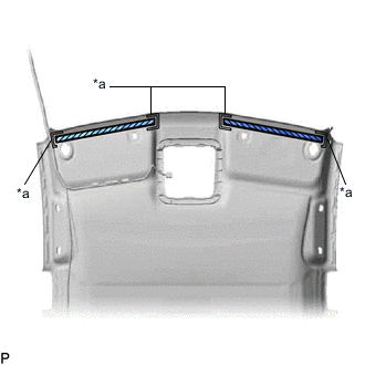
*a Marking w/ Front Silencer Pad:
-
Remove the release paper from 2 new No. 3 roof silencer pads.
Tech Tips
After removing the release paper, keep the exposed adhesive free from foreign matter.
-
Align the markings on the roof headlining with the No. 3 roof silencer pads and install the pads as shown in the illustration.
-
-
-
INSTALL NO. 4 ROOF SILENCER PAD (for Standard Roof)
-
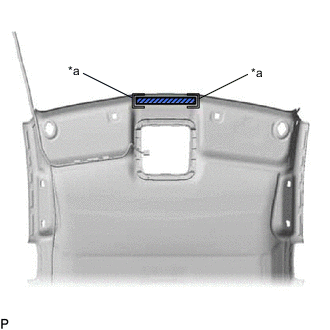
*a Marking w/ Front Silencer Pad:
-
Remove the release paper from a new No. 4 roof silencer pad.
Tech Tips
After removing the release paper, keep the exposed adhesive free from foreign matter.
-
Align the markings on the roof headlining with the No. 4 roof silencer pad and install the pad as shown in the illustration.
-
-
-
INSTALL NO. 3 ANTENNA CORD SUB-ASSEMBLY
-
INSTALL VANITY LIGHT ASSEMBLY (w/ Vanity Light)
-
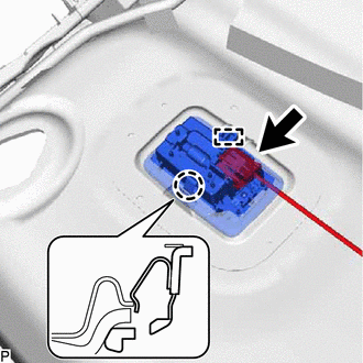
Engage the guide and claw to install the vanity light assembly.
Tech Tips
Use the same procedure for the RH side and LH side.
-
Connect the connector.
Tech Tips
Use the same procedure for the RH side and LH side.
-
-
INSTALL NO. 1 ROOM LIGHT ASSEMBLY (for Push Switch Type)
-
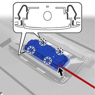
Engage the 4 claws to install the No. 1 room light assembly.
-
Connect the connector.
-