FRONT CONSOLE BOX REMOVAL
PROCEDURE
-
PRECAUTION
Note
After turning the power switch off, waiting time maybe required before disconnecting the cable from the auxiliary battery negative (-) terminal. Therefore,make sure to read the disconnecting the cable from the auxiliary battery negative (-) terminal noticesbefore proceeding with work
-
REMOVE BATTERY BOX COVER
-
DISCONNECT CABLE FROM AUXILIARY BATTERY NEGATIVE TERMINAL
Note
When disconnecting the cable, some systems need to be initialized after the cable is reconnected.
-
REMOVE LOWER NO. 2 INSTRUMENT PANEL FINISH PANEL
-
REMOVE FRONT NO. 1 CONSOLE BOX INSERT
-
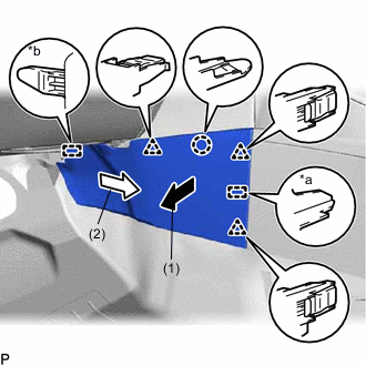
*a Guide <A> *b Guide <B> Pull the front No. 1 console box insert in the direction indicated by the arrow (1) to disengage the claw, 3 clips and guide <A>.
-
Pull the front No. 1 console box insert in the direction indicated by the arrow (2) to disengage the guide <B> to remove the front No. 1 console box insert.
-
-
REMOVE FRONT NO. 2 CONSOLE BOX INSERT
-
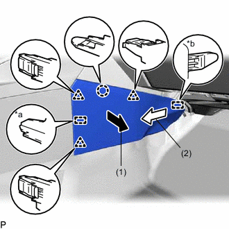
*a Guide <A> *b Guide <B> Pull the front No. 2 console box insert in the direction indicated by the arrow (1) to disengage the claw, 3 clips and guide <A>.
-
Pull the front No. 2 console box insert in the direction indicated by the arrow (2) to disengage the guide <B> to remove the front No. 2 console box insert.
-
-
REMOVE UPPER CONSOLE PANEL SUB-ASSEMBLY
-
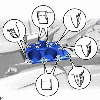
Disengage the 4 claws and 5 clips.
-
Disconnect each connector and remove the upper console panel sub-assembly.
-
-
REMOVE UPPER CONSOLE PANEL
-
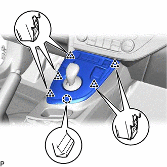
Disengage the 5 clips and claw.
-
Disconnect each connector and remove the upper console panel.
-
-
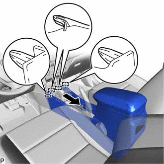
REMOVE LOWER CONSOLE COVER
-
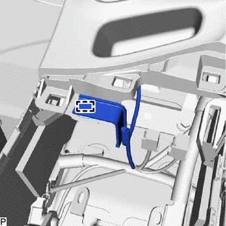
Disengage the clamp.
-
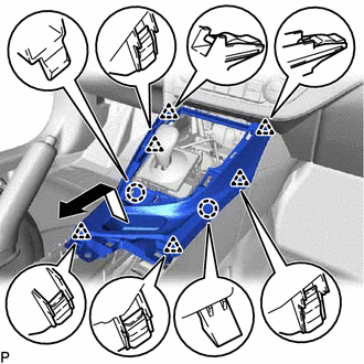
Disengage the 2 claws and 6 clips and remove the lower console cover as shown in the illustration.
-
-
REMOVE REAR CONSOLE BOX COVER (w/o Power Outlet Socket)
-
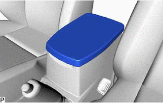
Remove the rear console box cover.
-
-
REMOVE CONSOLE BOX CARPET
-
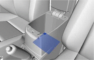
Remove the console box carpet.
-
-
REMOVE REAR CONSOLE BOX ASSEMBLY
-
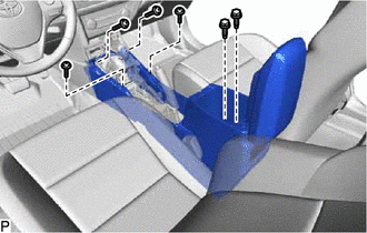
Remove the 2 bolts and 4 screws.
-
Disengage the 4 guides and remove the rear console box assembly as shown in the illustration.
-