POWER WINDOW CONTROL SYSTEM(for Models with Jam Protection Function on 4 Windows) TERMINALS OF ECU
-
POWER WINDOW REGULATOR MASTER SWITCH ASSEMBLY

*A for LHD *B for RHD
-
Disconnect the H12*1 or G3*2 power window regulator master switch assembly connector.
-
*1: for LHD
-
*2: for RHD
-
-
Measure the voltage and resistance according to the value(s) in the table below.
Tech Tips
Measure the values on the wire harness side with the connector disconnected.
for LHD Tester Connection Wiring Color Terminal Description Condition Specified Condition H12-11 (B) - H12-12 (GND) W - W-B Power supply Power switch off 11 to 14 V H12-12 (GND) - Body ground W-B - Body ground Ground Always Below 1 Ω for RHD Tester Connection Wiring Color Terminal Description Condition Specified Condition G3-11 (B) - G3-12 (GND) W - W-B Power supply Power switch off 11 to 14 V G3-12 (GND) - Body ground W-B - Body ground Ground Always Below 1 Ω If the result is not as specified, there may be a malfunction in the wire harness.
-
Reconnect the H12*1 or G3*2 power window regulator master switch assembly connector.
-
*1: for LHD
-
*2: for RHD
-
-
Measure the voltage according to the value(s) in the table below.
for LHD Tester Connection Wiring Color Terminal Description Condition Specified Condition H12-15 (DOWN) - H12-12 (GND) B - W-B Power window motor DOWN output Power switch on (IG), driver door power window regulator switch not pushed or pulled 11 to 14 V H12-15 (DOWN) - H12-12 (GND) B - W-B Power window motor DOWN output Power switch on (IG), driver door power window moving, driver door power window regulator switch pushed halfway down (Manual operation) Below 1 V H12-18 (LED) - H12-12 (GND) LG - W-B LED illumination signal Power switch on (IG) 11 to 14 V H12-18 (LED) - H12-12 (GND) LG - W-B LED illumination signal Power switch turned off Below 1 V H12-20 (UP) - H12-12 (GND) W - W-B Power window motor UP output Power switch on (IG), driver door power window regulator switch not pushed or pulled 11 to 14 V H12-20 (UP) - H12-12 (GND) W - W-B Power window motor UP output Power switch on (IG), driver door power window moving, driver door power window regulator switch pulled halfway up (Manual operation) Below 1 V for RHD Tester Connection Wiring Color Terminal Description Condition Specified Condition G3-15 (DOWN) - G3-12 (GND) B - W-B Power window motor DOWN output Power switch on (IG), driver door power window regulator switch not pushed or pulled 11 to 14 V G3-15 (DOWN) - G3-12 (GND) B - W-B Power window motor DOWN output Power switch on (IG), driver door power window moving, driver door power window regulator switch pushed halfway down (Manual operation) Below 1 V G3-18 (LED) - G3-12 (GND) LG - W-B LED illumination signal Power switch on (IG) 11 to 14 V G3-18 (LED) - G3-12 (GND) LG - W-B LED illumination signal Power switch turned off Below 1 V G3-20 (UP) - G3-12 (GND) W - W-B Power window motor UP output Power switch on (IG), driver door power window regulator switch not pushed or pulled 11 to 14 V G3-20 (UP) - G3-12 (GND) W - W-B Power window motor UP output Power switch on (IG), driver door power window moving, driver door power window regulator switch pulled halfway up (Manual operation) Below 1 V If the result is not as specified, the power window regulator master switch assembly may be malfunctioning.
-
-
CHECK POWER WINDOW REGULATOR SWITCH ASSEMBLY

*A for LHD *B for RHD
-
Disconnect the G10*1 or H3*2 power window regulator switch assembly connector.
-
*1: for LHD
-
*2: for RHD
-
-
Measure the resistance according to the value(s) in the table below.
Tech Tips
Measure the values on the wire harness side with the connector disconnected.
for LHD Tester Connection Wiring Color Terminal Description Condition Specified Condition G10-1 (GND) - Body ground W-B - Body ground Ground Always Below 1 Ω for RHD Tester Connection Wiring Color Terminal Description Condition Specified Condition H3-1 (GND) - Body ground W-B - Body ground Ground Always Below 1 Ω If the result is not as specified, there may be a malfunction in the wire harness.
-
Reconnect the G10*1 or H3*2 power window regulator switch assembly connector.
-
*1: for LHD
-
*2: for RHD
-
-
Measure the voltage according to the value(s) in the table below.
for LHD Tester Connection Wiring Color Terminal Description Condition Specified Condition G10-4 (LED) - G10-1 (GND) LG - W-B LED illumination signal Power switch on (IG) 11 to 14 V G10-4 (LED) - G10-1 (GND) LG - W-B LED illumination signal Power switch turned off Below 1 V G10-6 (UP) - G10-1 (GND) B - W-B Power window motor UP output Power switch on (IG), power window regulator switch assembly not pushed or pulled 11 to 14 V G10-6 (UP) - G10-1 (GND) B - W-B Power window motor UP output Power switch on (IG), front passenger door power window moving, power window regulator switch assembly pulled halfway up (Manual operation) Below 1 V G10-6 (UP) - G10-1 (GND) B - W-B Power window motor UP output Power switch on (IG), front passenger door power window fully open 11 to 14 V G10-6 (UP) - G10-1 (GND) B - W-B Power window motor UP output Power switch on (IG), front passenger door power window moving, power window regulator switch assembly fully pulled up (Auto operation) Below 1 V G10-6 (UP) - G10-1 (GND) B - W-B Power window motor UP output Power switch on (IG), front passenger door power window fully closed 11 to 14 V G10-7 (DOWN) - G10-1 (GND) P - W-B Power window motor DOWN output Power switch on (IG), power window regulator switch assembly not pushed or pulled 11 to 14 V G10-7 (DOWN) - G10-1 (GND) P - W-B Power window motor DOWN output Power switch on (IG), front passenger door power window moving, power window regulator switch assembly pushed halfway down (Manual operation) Below 1 V G10-7 (DOWN) - G10-1 (GND) P - W-B Power window motor DOWN output Power switch on (IG), front passenger door power window fully closed 11 to 14 V G10-7 (DOWN) - G10-1 (GND) P - W-B Power window motor DOWN output Power switch on (IG), front passenger door power window moving, power window regulator switch assembly fully pushed down (Auto operation) Below 1 V G10-7 (DOWN) - G10-1 (GND) P - W-B Power window motor DOWN output Power switch on (IG), front passenger door power window fully open 11 to 14 V G10-8 (AUTO) - G10-1 (GND) W - W-B Power window motor AUTO UP output Power switch on (IG), front passenger door power window fully open 11 to 14 V G10-8 (AUTO) - G10-1 (GND) W - W-B Power window motor AUTO UP output Power switch on (IG), front passenger door power window moving, power window regulator switch assembly fully pulled up (Auto operation) Below 1 V G10-8 (AUTO) - G10-1 (GND) W - W-B Power window motor AUTO UP output Power switch on (IG), front passenger door power window fully closed 11 to 14 V G10-8 (AUTO) - G10-1 (GND) W - W-B Power window motor AUTO DOWN output Power switch on (IG), front passenger door power window fully closed 11 to 14 V G10-8 (AUTO) - G10-1 (GND) W - W-B Power window motor AUTO DOWN output Power switch on (IG), front passenger door power window moving, power window regulator switch assembly fully pushed down (Auto operation) Below 1 V G10-8 (AUTO) - G10-1 (GND) W - W-B Power window motor AUTO DOWN output Power switch on (IG), front passenger door power window fully open 11 to 14 V for RHD Tester Connection Wiring Color Terminal Description Condition Specified Condition H3-4 (LED) - H3-1 (GND) LG - W-B LED illumination signal Power switch on (IG) 11 to 14 V H3-4 (LED) - H3-1 (GND) LG - W-B LED illumination signal Power switch turned off Below 1 V H3-6 (UP) - H3-1 (GND) B - W-B Power window motor UP output Power switch on (IG), power window regulator switch assembly not pushed or pulled 11 to 14 V H3-6 (UP) - H3-1 (GND) B - W-B Power window motor UP output Power switch on (IG), front passenger door power window moving, power window regulator switch assembly pulled halfway up (Manual operation) Below 1 V H3-6 (UP) - H3-1 (GND) B - W-B Power window motor UP output Power switch on (IG), front passenger door power window fully open 11 to 14 V H3-6 (UP) - H3-1 (GND) B - W-B Power window motor UP output Power switch on (IG), front passenger door power window moving, power window regulator switch assembly fully pulled up (Auto operation) Below 1 V H3-6 (UP) - H3-1 (GND) B - W-B Power window motor UP output Power switch on (IG), front passenger door power window fully closed 11 to 14 V H3-7 (DOWN) - H3-1 (GND) P - W-B Power window motor DOWN output Power switch on (IG), power window regulator switch assembly not pushed or pulled 11 to 14 V H3-7 (DOWN) - H3-1 (GND) P - W-B Power window motor DOWN output Power switch on (IG), front passenger door power window moving, power window regulator switch assembly pushed halfway down (Manual operation) Below 1 V H3-7 (DOWN) - H3-1 (GND) P - W-B Power window motor DOWN output Power switch on (IG), front passenger door power window fully closed 11 to 14 V H3-7 (DOWN) - H3-1 (GND) P - W-B Power window motor DOWN output Power switch on (IG), front passenger door power window moving, power window regulator switch assembly fully pushed down (Auto operation) Below 1 V H3-7 (DOWN) - H3-1 (GND) P - W-B Power window motor DOWN output Power switch on (IG), front passenger door power window fully open 11 to 14 V H3-8 (AUTO) - H3-1 (GND) W - W-B Power window motor AUTO UP output Power switch on (IG), front passenger door power window fully open 11 to 14 V H3-8 (AUTO) - H3-1 (GND) W - W-B Power window motor AUTO UP output Power switch on (IG), front passenger door power window moving, power window regulator switch assembly fully pulled up (Auto operation) Below 1 V H3-8 (AUTO) - H3-1 (GND) W - W-B Power window motor AUTO UP output Power switch on (IG), front passenger door power window fully closed 11 to 14 V H3-8 (AUTO) - H3-1 (GND) W - W-B Power window motor AUTO DOWN output Power switch on (IG), front passenger door power window fully closed 11 to 14 V H3-8 (AUTO) - H3-1 (GND) W - W-B Power window motor AUTO DOWN output Power switch on (IG), front passenger door power window moving, power window regulator switch assembly fully pushed down (Auto operation) Below 1 V H3-8 (AUTO) - H3-1 (GND) W - W-B Power window motor AUTO DOWN output Power switch on (IG), front passenger door power window fully open 11 to 14 V If the result is not as specified, the power window regulator switch assembly may be malfunctioning.
-
-
CHECK REAR POWER WINDOW REGULATOR SWITCH ASSEMBLY (for LH Door)

-
Disconnect the K1 rear power window regulator switch assembly (for LH door) connector.
-
Measure the resistance according to the value(s) in the table below.
Tech Tips
Measure the values on the wire harness side with the connector disconnected.
Tester Connection Wiring Color Terminal Description Condition Specified Condition K1-1 (GND) - Body ground W-B - Body ground Ground Always Below 1 Ω If the result is not as specified, there may be a malfunction in the wire harness.
-
Reconnect the K1 rear power window regulator switch assembly (for LH door) connector.
-
Measure the voltage according to the value(s) in the table below.
Tester Connection Wiring Color Terminal Description Condition Specified Condition K1-4 (LED) - K1-1 (GND) LG - W-B LED illumination signal Power switch on (IG) 11 to 14 V K1-4 (LED) - K1-1 (GND) LG - W-B LED illumination signal Power switch turned off Below 1 V K1-6 (UP) - K1-1 (GND) B - W-B Power window motor UP output Power switch on (IG), rear power window regulator switch assembly (for LH door) not pushed or pulled 11 to 14 V K1-6 (UP) - K1-1 (GND) B - W-B Power window motor UP output Power switch on (IG), rear LH door power window moving, rear power window regulator switch assembly (for LH door) pulled halfway up (Manual operation) Below 1 V K1-6 (UP) - K1-1 (GND) B - W-B Power window motor UP output Power switch on (IG), rear LH door power window fully open 11 to 14 V K1-6 (UP) - K1-1 (GND) B - W-B Power window motor UP output Power switch on (IG), rear LH door power window moving, rear power window regulator switch assembly (for LH door) fully pulled up (Auto operation) Below 1 V K1-6 (UP) - K1-1 (GND) B - W-B Power window motor UP output Power switch on (IG), rear LH door power window fully closed 11 to 14 V K1-7 (DOWN) - K1-1 (GND) P - W-B Power window motor DOWN output Power switch on (IG), rear power window regulator switch assembly (for LH door) not pushed or pulled 11 to 14 V K1-7 (DOWN) - K1-1 (GND) P - W-B Power window motor DOWN output Power switch on (IG), rear LH door power window moving, rear power window regulator switch assembly (for LH door) pushed halfway down (Manual operation) Below 1 V K1-7 (DOWN) - K1-1 (GND) P - W-B Power window motor DOWN output Power switch on (IG), rear LH door power window fully closed 11 to 14 V K1-7 (DOWN) - K1-1 (GND) P - W-B Power window motor DOWN output Power switch on (IG), rear LH door power window moving, rear power window regulator switch assembly (for LH door) fully pushed down (Auto operation) Below 1 V K1-7 (DOWN) - K1-1 (GND) P - W-B Power window motor DOWN output Power switch on (IG), rear LH door power window fully open 11 to 14 V K1-8 (AUTO) - K1-1 (GND) W - W-B Power window motor AUTO UP output Power switch on (IG), rear LH door power window fully open 11 to 14 V K1-8 (AUTO) - K1-1 (GND) W - W-B Power window motor AUTO UP output Power switch on (IG), rear LH door power window moving, rear power window regulator switch assembly (for LH door) fully pulled up (Auto operation) Below 1 V K1-8 (AUTO) - K1-1 (GND) W - W-B Power window motor AUTO UP output Power switch on (IG), rear LH door power window fully closed 11 to 14 V K1-8 (AUTO) - K1-1 (GND) W - W-B Power window motor AUTO DOWN output Power switch on (IG), rear LH door power window fully closed 11 to 14 V K1-8 (AUTO) - K1-1 (GND) W - W-B Power window motor AUTO DOWN output Power switch on (IG), rear LH door power window moving, rear power window regulator switch assembly (for LH door) fully pushed down (Auto operation) Below 1 V K1-8 (AUTO) - K1-1 (GND) W - W-B Power window motor AUTO DOWN output Power switch on (IG), rear LH door power window fully open 11 to 14 V If the result is not as specified, the rear power window regulator switch assembly (for LH door) may be malfunctioning.
-
-
CHECK REAR POWER WINDOW REGULATOR SWITCH ASSEMBLY (for RH Door)

-
Disconnect the J1 rear power window regulator switch assembly (for RH door) connector.
-
Measure the resistance according to the value(s) in the table below.
Tech Tips
Measure the values on the wire harness side with the connector disconnected.
Tester Connection Wiring Color Terminal Description Condition Specified Condition J1-1 (GND) - Body ground W-B - Body ground Ground Always Below 1 Ω If the result is not as specified, there may be a malfunction in the wire harness.
-
Reconnect the J1 rear power window regulator switch assembly (for RH door) connector.
-
Measure the voltage according to the value(s) in the table below.
Tester Connection Wiring Color Terminal Description Condition Specified Condition J1-4 (LED) - J1-1 (GND) LG - W-B LED illumination signal Power switch on (IG) 11 to 14 V J1-4 (LED) - J1-1 (GND) LG - W-B LED illumination signal Power switch turned off Below 1 V J1-6 (UP) - J1-1 (GND) B - W-B Power window motor UP output Power switch on (IG), rear power window regulator switch assembly (for RH door) not pushed or pulled 11 to 14 V J1-6 (UP) - J1-1 (GND) B - W-B Power window motor UP output Power switch on (IG), rear RH door power window moving, rear power window regulator switch assembly (for RH door) pulled halfway up (Manual operation) Below 1 V J1-6 (UP) - J1-1 (GND) B - W-B Power window motor UP output Power switch on (IG), rear RH door power window fully open 11 to 14 V J1-6 (UP) - J1-1 (GND) B - W-B Power window motor UP output Power switch on (IG), rear RH door power window moving, rear power window regulator switch assembly (for RH door) fully pulled up (Auto operation) Below 1 V J1-6 (UP) - J1-1 (GND) B - W-B Power window motor UP output Power switch on (IG), rear RH door power window fully closed 11 to 14 V J1-7 (DOWN) - J1-1 (GND) P - W-B Power window motor DOWN output Power switch on (IG), rear power window regulator switch assembly (for RH door) not pushed or pulled 11 to 14 V J1-7 (DOWN) - J1-1 (GND) P - W-B Power window motor DOWN output Power switch on (IG), rear RH door power window moving, rear power window regulator switch assembly (for RH door) pushed halfway down (Manual operation) Below 1 V J1-7 (DOWN) - J1-1 (GND) P - W-B Power window motor DOWN output Power switch on (IG), rear RH door power window fully closed 11 to 14 V J1-7 (DOWN) - J1-1 (GND) P - W-B Power window motor DOWN output Power switch on (IG), rear RH door power window moving, rear power window regulator switch assembly (for RH door) fully pushed down (Auto operation) Below 1 V J1-7 (DOWN) - J1-1 (GND) P - W-B Power window motor DOWN output Power switch on (IG), rear RH door power window fully open 11 to 14 V J1-8 (AUTO) - J1-1 (GND) W - W-B Power window motor AUTO UP output Power switch on (IG), rear RH door power window fully open 11 to 14 V J1-8 (AUTO) - J1-1 (GND) W - W-B Power window motor AUTO UP output Power switch on (IG), rear RH door power window moving, rear power window regulator switch assembly (for RH door) fully pulled up (Auto operation) Below 1 V J1-8 (AUTO) - J1-1 (GND) W - W-B Power window motor AUTO UP output Power switch on (IG), rear RH door power window fully closed 11 to 14 V J1-8 (AUTO) - J1-1 (GND) W - W-B Power window motor AUTO DOWN output Power switch on (IG), rear RH door power window fully closed 11 to 14 V J1-8 (AUTO) - J1-1 (GND) W - W-B Power window motor AUTO DOWN output Power switch on (IG), rear RH door power window moving, rear power window regulator switch assembly (for RH door) fully pushed down (Auto operation) Below 1 V J1-8 (AUTO) - J1-1 (GND) W - W-B Power window motor AUTO DOWN output Power switch on (IG), rear RH door power window fully open 11 to 14 V If the result is not as specified, the rear power window regulator switch assembly (for RH door) may be malfunctioning.
-
-
CHECK FRONT DOOR WINDOW REGULATOR ASSEMBLY (for Driver Door)

*A for LHD *B for RHD
-
Disconnect the H14*1 or G5*2 front door window regulator assembly (for driver door) connector.
-
*1: for LHD
-
*2: for RHD
-
-
Measure the voltage and resistance according to the value(s) in the table below.
Tech Tips
Measure the values on the wire harness side with the connector disconnected.
for LHD Tester Connection Wiring Color Terminal Description Condition Specified Condition H14-1 (GND) - Body ground W-B - Body ground Ground Always Below 1 Ω H14-2 (B) - Body ground GR - Body ground Power supply Power switch off 11 to 14 V for RHD Tester Connection Wiring Color Terminal Description Condition Specified Condition G5-1 (GND) - Body ground W-B - Body ground Ground Always Below 1 Ω G5-2 (B) - Body ground GR - Body ground Power supply Power switch off 11 to 14 V If the result is not as specified, there may be a malfunction in the wire harness.
-
Reconnect the H14*1 or G5*2 front door window regulator assembly (for driver door) connector.
-
*1: for LHD
-
*2: for RHD
-
-
Measure the voltage according to the value(s) in the table below.
for LHD Tester Connection Wiring Color Terminal Description Condition Specified Condition H14-5 (LED) - H14-1 (GND) LG - W-B LED illumination signal Power switch on (IG) 11 to 14 V H14-5 (LED) - H14-1 (GND) LG - W-B LED illumination signal Power switch turned off Below 1 V H14-7 (DOWN) - H14-1 (GND) B - W-B Power window motor DOWN input Power switch on (IG), power window regulator master switch assembly (driver door power window regulator switch) not pushed or pulled 11 to 14 V H14-7 (DOWN) - H14-1 (GND) B - W-B Power window motor DOWN input Power switch on (IG), driver door power window moving, power window regulator master switch assembly (driver door power window regulator switch) pushed halfway down (Manual operation) Below 1 V H14-7 (DOWN) - H14-1 (GND) B - W-B Power window motor DOWN input Power switch on (IG), driver door power window fully closed 11 to 14 V H14-7 (DOWN) - H14-1 (GND) B - W-B Power window motor DOWN input Power switch on (IG), driver door power window moving, power window regulator master switch assembly (driver door power window regulator switch) fully pushed down (Auto operation) Below 1 V H14-7 (DOWN) - H14-1 (GND) B - W-B Power window motor DOWN input Power switch on (IG), driver door power window fully open 11 to 14 V H14-10 (UP) - H14-1 (GND) W - W-B Power window motor UP input Power switch on (IG), power window regulator master switch assembly (driver door power window regulator switch) not pushed or pulled 11 to 14 V H14-10 (UP) - H14-1 (GND) W - W-B Power window motor UP input Power switch on (IG), driver door power window moving, power window regulator master switch assembly (driver door power window regulator switch) pulled halfway up (Manual operation) Below 1 V H14-10 (UP) - H14-1 (GND) W - W-B Power window motor UP input Power switch on (IG), power window regulator master switch assembly (driver door power window regulator switch) fully open 11 to 14 V H14-10 (UP) - H14-1 (GND) W - W-B Power window motor UP input Power switch on (IG), driver door power window moving, power window regulator master switch assembly (driver door power window regulator switch) fully pulled up (Auto operation) Below 1 V H14-10 (UP) - H14-1 (GND) W - W-B Power window motor UP input Power switch on (IG), driver door power window fully closed 11 to 14 V for RHD Tester Connection Wiring Color Terminal Description Condition Specified Condition G5-5 (LED) - G5-1 (GND) LG - W-B LED illumination signal Power switch on (IG) 11 to 14 V G5-5 (LED) - G5-1 (GND) LG - W-B LED illumination signal Power switch turned off Below 1 V G5-7 (DOWN) - G5-1 (GND) B - W-B Power window motor DOWN input Power switch on (IG), power window regulator master switch assembly (driver door power window regulator switch) not pushed or pulled 11 to 14 V G5-7 (DOWN) - G5-1 (GND) B - W-B Power window motor DOWN input Power switch on (IG), driver door power window moving, power window regulator master switch assembly (driver door power window regulator switch) pushed halfway down (Manual operation) Below 1 V G5-7 (DOWN) - G5-1 (GND) B - W-B Power window motor DOWN input Power switch on (IG), driver door power window fully closed 11 to 14 V G5-7 (DOWN) - G5-1 (GND) B - W-B Power window motor DOWN input Power switch on (IG), driver door power window moving, power window regulator master switch assembly (driver door power window regulator switch) fully pushed down (Auto operation) Below 1 V G5-7 (DOWN) - G5-1 (GND) B - W-B Power window motor DOWN input Power switch on (IG), driver door power window fully open 11 to 14 V G5-10 (UP) - G5-1 (GND) W - W-B Power window motor UP input Power switch on (IG), power window regulator master switch assembly (driver door power window regulator switch) not pushed or pulled 11 to 14 V G5-10 (UP) - G5-1 (GND) W - W-B Power window motor UP input Power switch on (IG), driver door power window moving, power window regulator master switch assembly (driver door power window regulator switch) pulled halfway up (Manual operation) Below 1 V G5-10 (UP) - G5-1 (GND) W - W-B Power window motor UP input Power switch on (IG), power window regulator master switch assembly (driver door power window regulator switch) fully open 11 to 14 V G5-10 (UP) - G5-1 (GND) W - W-B Power window motor UP input Power switch on (IG), driver door power window moving, power window regulator master switch assembly (driver door power window regulator switch) fully pulled up (Auto operation) Below 1 V G5-10 (UP) - G5-1 (GND) W - W-B Power window motor UP input Power switch on (IG), driver door power window fully closed 11 to 14 V If the result is not as specified, the front door window regulator assembly (for driver door) may be malfunctioning.
-
-
CHECK FRONT DOOR WINDOW REGULATOR ASSEMBLY (for Passenger Door)

*A for LHD *B for RHD
-
Disconnect the G13*1 or H4*2 front door window regulator assembly (for passenger door) connector.
-
*1: for LHD
-
*2: for RHD
-
-
Measure the voltage and resistance according to the value(s) in the table below.
Tech Tips
Measure the values on the wire harness side with the connector disconnected.
for LHD Tester Connection Wiring Color Terminal Description Condition Specified Condition G13-1 (GND) - Body ground W-B - Body ground Ground Always Below 1 Ω G13-2 (B) - Body ground GR - Body ground Power supply Power switch off 11 to 14 V for RHD Tester Connection Wiring Color Terminal Description Condition Specified Condition H4-1 (GND) - Body ground W-B - Body ground Ground Always Below 1 Ω H4-2 (B) - Body ground GR - Body ground Power supply Power switch off 11 to 14 V If the result is not as specified, there may be a malfunction in the wire harness.
-
Reconnect the G13*1 or H4*2 front door window regulator assembly (for passenger door) connector.
-
*1: for LHD
-
*2: for RHD
-
-
Measure the voltage according to the value(s) in the table below.
for LHD Tester Connection Wiring Color Terminal Description Condition Specified Condition G13-4 (AUTO) - G13-1 (GND) W - W-B Power window motor AUTO UP input Power switch on (IG), front passenger door power window fully open 11 to 14 V G13-4 (AUTO) - G13-1 (GND) W - W-B Power window motor AUTO UP input Power switch on (IG), front passenger door power window moving, power window regulator switch assembly fully pulled up (Auto operation) Below 1 V G13-4 (AUTO) - G13-1 (GND) W - W-B Power window motor AUTO UP input Power switch on (IG), front passenger door power window fully closed 11 to 14 V G13-4 (AUTO) - G13-1 (GND) W - W-B Power window motor AUTO DOWN input Power switch on (IG), front passenger door power window fully closed 11 to 14 V G13-4 (AUTO) - G13-1 (GND) W - W-B Power window motor AUTO DOWN input Power switch on (IG), front passenger door power window moving, power window regulator switch assembly fully pushed down (Auto operation) Below 1 V G13-4 (AUTO) - G13-1 (GND) W - W-B Power window motor AUTO DOWN input Power switch on (IG), front passenger door power window fully open 11 to 14 V G13-5 (LED) - G13-1 (GND) LG - W-B LED illumination signal Power switch on (IG) 11 to 14 V G13-5 (LED) - G13-1 (GND) LG - W-B LED illumination signal Power switch turned off Below 1 V G13-7 (DOWN) - G13-1 (GND) P - W-B Power window motor DOWN input Power switch on (IG), power window regulator switch assembly not pushed or pulled 11 to 14 V G13-7 (DOWN) - G13-1 (GND) P - W-B Power window motor DOWN input Power switch on (IG), front passenger door power window moving, power window regulator switch assembly pushed halfway down (Manual operation) Below 1 V G13-7 (DOWN) - G13-1 (GND) P - W-B Power window motor DOWN input Power switch on (IG), front passenger door power window fully closed 11 to 14 V G13-7 (DOWN) - G13-1 (GND) P - W-B Power window motor DOWN input Power switch on (IG), front passenger door power window moving, power window regulator switch assembly fully pushed down (Auto operation) Below 1 V G13-7 (DOWN) - G13-1 (GND) P - W-B Power window motor DOWN input Power switch on (IG), front passenger door power window fully open 11 to 14 V G13-10 (UP) - G13-1 (GND) B - W-B Power window motor UP input Power switch on (IG), power window regulator switch assembly not pushed or pulled 11 to 14 V G13-10 (UP) - G13-1 (GND) B - W-B Power window motor UP input Power switch on (IG), front passenger door power window moving, power window regulator switch assembly pulled halfway up (Manual operation) Below 1 V G13-10 (UP) - G13-1 (GND) B - W-B Power window motor UP input Power switch on (IG), front passenger door power window fully open 11 to 14 V G13-10 (UP) - G13-1 (GND) B - W-B Power window motor UP input Power switch on (IG), front passenger door power window moving, power window regulator switch assembly fully pulled up (Auto operation) Below 1 V G13-10 (UP) - G13-1 (GND) B - W-B Power window motor UP input Power switch on (IG), front passenger door power window fully closed 11 to 14 V for RHD Tester Connection Wiring Color Terminal Description Condition Specified Condition H4-4 (AUTO) - H4-1 (GND) W - W-B Power window motor AUTO UP input Power switch on (IG), front passenger door power window fully open 11 to 14 V H4-4 (AUTO) - H4-1 (GND) W - W-B Power window motor AUTO UP input Power switch on (IG), front passenger door power window moving, power window regulator switch assembly fully pulled up (Auto operation) Below 1 V H4-4 (AUTO) - H4-1 (GND) W - W-B Power window motor AUTO UP input Power switch on (IG), front passenger door power window fully closed 11 to 14 V H4-4 (AUTO) - H4-1 (GND) W - W-B Power window motor AUTO DOWN input Power switch on (IG), front passenger door power window fully closed 11 to 14 V H4-4 (AUTO) - H4-1 (GND) W - W-B Power window motor AUTO DOWN input Power switch on (IG), front passenger door power window moving, power window regulator switch assembly fully pushed down (Auto operation) Below 1 V H4-4 (AUTO) - H4-1 (GND) W - W-B Power window motor AUTO DOWN input Power switch on (IG), front passenger door power window fully open 11 to 14 V H4-5 (LED) - H4-1 (GND) LG - W-B LED illumination signal Power switch on (IG) 11 to 14 V H4-5 (LED) - H4-1 (GND) LG - W-B LED illumination signal Power switch turned off Below 1 V H4-7 (DOWN) - H4-1 (GND) P - W-B Power window motor DOWN input Power switch on (IG), power window regulator switch assembly not pushed or pulled 11 to 14 V H4-7 (DOWN) - H4-1 (GND) P - W-B Power window motor DOWN input Power switch on (IG), front passenger door power window moving, power window regulator switch assembly pushed halfway down (Manual operation) Below 1 V H4-7 (DOWN) - H4-1 (GND) P - W-B Power window motor DOWN input Power switch on (IG), front passenger door power window fully closed 11 to 14 V H4-7 (DOWN) - H4-1 (GND) P - W-B Power window motor DOWN input Power switch on (IG), front passenger door power window moving, power window regulator switch assembly fully pushed down (Auto operation) Below 1 V H4-7 (DOWN) - H4-1 (GND) P - W-B Power window motor DOWN input Power switch on (IG), front passenger door power window fully open 11 to 14 V H4-10 (UP) - H4-1 (GND) B - W-B Power window motor UP input Power switch on (IG), power window regulator switch assembly not pushed or pulled 11 to 14 V H4-10 (UP) - H4-1 (GND) B - W-B Power window motor UP input Power switch on (IG), front passenger door power window moving, power window regulator switch assembly pulled halfway up (Manual operation) Below 1 V H4-10 (UP) - H4-1 (GND) B - W-B Power window motor UP input Power switch on (IG), front passenger door power window fully open 11 to 14 V H4-10 (UP) - H4-1 (GND) B - W-B Power window motor UP input Power switch on (IG), front passenger door power window moving, power window regulator switch assembly fully pulled up (Auto operation) Below 1 V H4-10 (UP) - H4-1 (GND) B - W-B Power window motor UP input Power switch on (IG), front passenger door power window fully closed 11 to 14 V If the result is not as specified, the front door window regulator assembly (for passenger door) may be malfunctioning.
-
-
CHECK REAR DOOR WINDOW REGULATOR ASSEMBLY (for LH Door)

-
Disconnect the K3 rear door window regulator assembly (for LH door) connector.
-
Measure the voltage and resistance according to the value(s) in the table below.
Tech Tips
Measure the values on the wire harness side with the connector disconnected.
Tester Connection Wiring Color Terminal Description Condition Specified Condition K3-1 (GND) - Body ground W-B - Body ground Ground Always Below 1 Ω K3-2 (B) - Body ground LA-P - Body ground Power supply Power switch off 11 to 14 V If the result is not as specified, there may be a malfunction in the wire harness.
-
Reconnect the K3 rear door window regulator assembly (for LH door) connector.
-
Measure the voltage according to the value(s) in the table below.
Tester Connection Wiring Color Terminal Description Condition Specified Condition K3-4 (AUTO) - K3-1 (GND) W - W-B Power window motor AUTO UP input Power switch on (IG), rear LH door power window fully open 11 to 14 V K3-4 (AUTO) - K3-1 (GND) W - W-B Power window motor AUTO UP input Power switch on (IG), rear LH door power window moving, rear power window regulator switch assembly (for LH door) fully pulled up (Auto operation) Below 1 V K3-4 (AUTO) - K3-1 (GND) W - W-B Power window motor AUTO UP input Power switch on (IG), rear LH door power window fully closed 11 to 14 V K3-4 (AUTO) - K3-1 (GND) W - W-B Power window motor AUTO DOWN input Power switch on (IG), rear LH door power window fully closed 11 to 14 V K3-4 (AUTO) - K3-1 (GND) W - W-B Power window motor AUTO DOWN input Power switch on (IG), rear LH door power window moving, rear power window regulator switch assembly (for LH door) fully pushed down (Auto operation) Below 1 V K3-4 (AUTO) - K3-1 (GND) W - W-B Power window motor AUTO DOWN input Power switch on (IG), rear LH door power window fully open 11 to 14 V K3-5 (LED) - K3-1 (GND) LG - W-B LED illumination signal Power switch on (IG) 11 to 14 V K3-5 (LED) - K3-1 (GND) LG - W-B LED illumination signal Power switch turned off Below 1 V K3-7 (DOWN) - K3-1 (GND) P - W-B Power window motor DOWN input Power switch on (IG), rear power window regulator switch assembly (for LH door) not pushed or pulled 11 to 14 V K3-7 (DOWN) - K3-1 (GND) P - W-B Power window motor DOWN input Power switch on (IG), rear LH door power window moving, rear power window regulator switch assembly (for LH door) pushed halfway down (Manual operation) Below 1 V K3-7 (DOWN) - K3-1 (GND) P - W-B Power window motor DOWN input Power switch on (IG), rear LH door power window fully closed 11 to 14 V K3-7 (DOWN) - K3-1 (GND) P - W-B Power window motor DOWN input Power switch on (IG), rear LH door power window moving, rear power window regulator switch assembly (for LH door) fully pushed down (Auto operation) Below 1 V K3-7 (DOWN) - K3-1 (GND) P - W-B Power window motor DOWN input Power switch on (IG), rear LH door power window fully open 11 to 14 V K3-10 (UP) - K3-1 (GND) B - W-B Power window motor UP input Power switch on (IG), rear power window regulator switch assembly (for LH door) not pushed or pulled 11 to 14 V K3-10 (UP) - K3-1 (GND) B - W-B Power window motor UP input Power switch on (IG), rear LH door power window moving, rear power window regulator switch assembly (for LH door) pulled halfway up (Manual operation) Below 1 V K3-10 (UP) - K3-1 (GND) B - W-B Power window motor UP input Power switch on (IG), rear LH door power window fully open 11 to 14 V K3-10 (UP) - K3-1 (GND) B - W-B Power window motor UP input Power switch on (IG), rear LH door power window moving, rear power window regulator switch assembly (for LH door) fully pulled up (Auto operation) Below 1 V K3-10 (UP) - K3-1 (GND) B - W-B Power window motor UP input Power switch on (IG), rear LH door power window fully closed 11 to 14 V If the result is not as specified, the rear door window regulator assembly (for LH door) may be malfunctioning.
-
-
CHECK REAR DOOR WINDOW REGULATOR ASSEMBLY (for RH Door)

-
Disconnect the J3 rear door window regulator assembly (for RH door) connector.
-
Measure the voltage and resistance according to the value(s) in the table below.
Tech Tips
Measure the values on the wire harness side with the connector disconnected.
Tester Connection Wiring Color Terminal Description Condition Specified Condition J3-1 (GND) - Body ground W-B - Body ground Ground Always Below 1 Ω J3-2 (B) - Body ground LA-L - Body ground Power supply Power switch off 11 to 14 V If the result is not as specified, there may be a malfunction in the wire harness.
-
Reconnect the J3 rear door window regulator assembly (for RH door) connector.
-
Measure the voltage according to the value(s) in the table below.
Tester Connection Wiring Color Terminal Description Condition Specified Condition J3-4 (AUTO) - J3-1 (GND) W - W-B Power window motor AUTO UP input Power switch on (IG), rear RH door power window fully open 11 to 14 V J3-4 (AUTO) - J3-1 (GND) W - W-B Power window motor AUTO UP input Power switch on (IG), rear RH door power window moving, rear power window regulator switch assembly (for RH door) fully pulled up (Auto operation) Below 1 V J3-4 (AUTO) - J3-1 (GND) W - W-B Power window motor AUTO UP input Power switch on (IG), rear RH door power window fully closed 11 to 14 V J3-4 (AUTO) - J3-1 (GND) W - W-B Power window motor AUTO DOWN input Power switch on (IG), rear RH door power window fully closed 11 to 14 V J3-4 (AUTO) - J3-1 (GND) W - W-B Power window motor AUTO DOWN input Power switch on (IG), rear RH door power window moving, rear power window regulator switch assembly (for RH door) fully pushed down (Auto operation) Below 1 V J3-4 (AUTO) - J3-1 (GND) W - W-B Power window motor AUTO DOWN input Power switch on (IG), rear RH door power window fully open 11 to 14 V J3-5 (LED) - J3-1 (GND) LG - W-B LED illumination signal Power switch on (IG) 11 to 14 V J3-5 (LED) - J3-1 (GND) LG - W-B LED illumination signal Power switch turned off Below 1 V J3-7 (DOWN) - J3-1 (GND) P - W-B Power window motor DOWN input Power switch on (IG), rear power window regulator switch assembly (for RH door) not pushed or pulled 11 to 14 V J3-7 (DOWN) - J3-1 (GND) P - W-B Power window motor DOWN input Power switch on (IG), rear RH door power window moving, rear power window regulator switch assembly (for RH door) pushed halfway down (Manual operation) Below 1 V J3-7 (DOWN) - J3-1 (GND) P - W-B Power window motor DOWN input Power switch on (IG), rear RH door power window fully closed 11 to 14 V J3-7 (DOWN) - J3-1 (GND) P - W-B Power window motor DOWN input Power switch on (IG), rear RH door power window moving, rear power window regulator switch assembly (for RH door) fully pushed down (Auto operation) Below 1 V J3-7 (DOWN) - J3-1 (GND) P - W-B Power window motor DOWN input Power switch on (IG), rear RH door power window fully open 11 to 14 V J3-10 (UP) - J3-1 (GND) B - W-B Power window motor UP input Power switch on (IG), rear power window regulator switch assembly (for RH door) not pushed or pulled 11 to 14 V J3-10 (UP) - J3-1 (GND) B - W-B Power window motor UP input Power switch on (IG), rear RH door power window moving, rear power window regulator switch assembly (for RH door) pulled halfway up (Manual operation) Below 1 V J3-10 (UP) - J3-1 (GND) B - W-B Power window motor UP input Power switch on (IG), rear RH door power window fully open 11 to 14 V J3-10 (UP) - J3-1 (GND) B - W-B Power window motor UP input Power switch on (IG), rear RH door power window moving, rear power window regulator switch assembly (for RH door) fully pulled up (Auto operation) Below 1 V J3-10 (UP) - J3-1 (GND) B - W-B Power window motor UP input Power switch on (IG), rear RH door power window fully closed 11 to 14 V If the result is not as specified, the rear door window regulator assembly (for RH door) may be malfunctioning.
-
-
CHECK INSTRUMENT PANEL JUNCTION BLOCK ASSEMBLY AND MAIN BODY ECU (MULTIPLEX NETWORK BODY ECU)
-
Disconnect the MB main body ECU (multiplex network body ECU) connector.
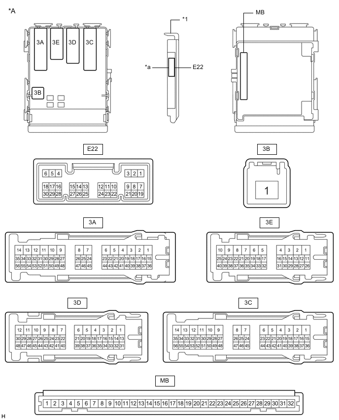
*A Main Body ECU (Multiplex Network Body ECU) with 1 Connector - - *1 Main Body ECU (Multiplex Network Body ECU) - - *a 1 Connector - - 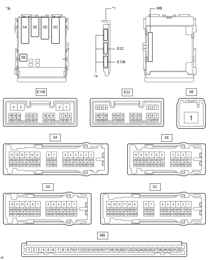
*A Main Body ECU (Multiplex Network Body ECU) with 3 Connectors - - *1 Main Body ECU (Multiplex Network Body ECU) - - *a 3 Connectors - - -
Measure the voltage and resistance according to the value(s) in the table below.
Tech Tips
Measure the values on the wire harness side with the connectors disconnected.
Tester Connection Wiring Color Terminal Description Condition Specified Condition MB-11 (GND1) - Body ground - Ground Always Below 1 Ω MB-30 (BECU) - Body ground - Auxiliary battery power supply Power switch off 11 to 14 V MB-29 (ACC) - Body ground - ACC power supply Power switch on (ACC) 11 to 14 V MB-29 (ACC) - Body ground - ACC power supply Power switch off Below 1 V MB-32 (IG) - Body ground - Power switch power supply Power switch on (IG) 11 to 14 V MB-32 (IG) - Body ground - Power switch power supply Power switch off Below 1 V If the result is not as specified, there may be a malfunction in the wire harness.
-
Reconnect the MB main body ECU (multiplex network body ECU) connector.
-
Measure the voltage according to the value(s) in the table below.
Tester Connection Wiring Color Terminal Description Condition Specified Condition 3E-25 (FLCY) - Body ground W - Body ground Front door courtesy switch LH input Front door LH open Below 1 V 3E-25 (FLCY) - Body ground W - Body ground Front door courtesy switch LH input Front door LH closed Pulse generation E22-19 (FRCY) - Body ground V - Body ground Front door courtesy switch RH input Front door RH open Below 1 V E22-19 (FRCY) - Body ground V - Body ground Front door courtesy switch RH input Front door RH closed Pulse generation If the result is not as specified, the main body ECU (multiplex network body ECU) or instrument panel junction block assembly may be malfunctioning.
-