UPPER INSTRUMENT PANEL REMOVAL
PROCEDURE
-
PRECAUTION
Note
After turning the power switch off, waiting time may be required before disconnecting the cable from the auxiliary negative (-) battery terminal. Therefore, make sure to read the disconnecting the cable from the auxiliary negative (-) battery terminal notices before proceeding with work.
-
REMOVE BATTERY BOX COVER
for Hatchback: Click here
for Wagon: Click here
-
DISCONNECT CABLE FROM AUXILIARY NEGATIVE BATTERY TERMINAL
CAUTION:
Wait at least 90 seconds after disconnecting the cable from the auxiliary negative (-) battery terminal to disable the SRS system.
Note
When disconnecting the cable, some systems need to be initialized after the cable is reconnected.
-
REMOVE LOWER NO. 2 INSTRUMENT PANEL FINISH PANEL
-
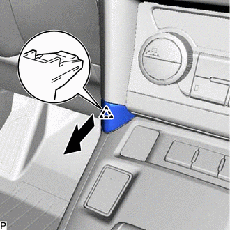
Disengage the clip and remove the lower No. 2 instrument panel finish panel as shown in the illustration.
-
-
REMOVE CENTER INSTRUMENT CLUSTER FINISH PANEL SUB-ASSEMBLY
-
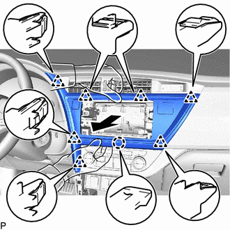
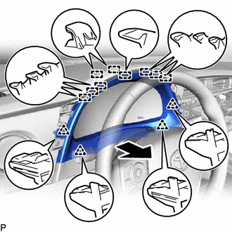
Hold the center instrumental cluster finish panel sub-assembly as shown in the illustration and pull it horizontally to disengage the claw and 7 clips.
Note
If the center instrument cluster finish panel sub-assembly is not held as shown in the illustration and pulled horizontally, the claw, clips and parts they engage may be damaged.
-
Disconnect each connecter and remove the center instrument cluster finish panel sub-assembly.
-
-
REMOVE NO. 1 METER HOOD CLUSTER
-
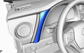

Protective tape Apply protective tape to the area shown in the illustration.
-
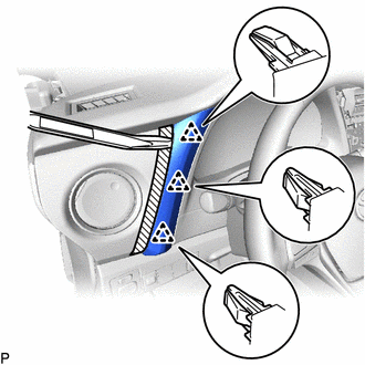
Using a moulding remover, disengage the 3 clips and remove the No. 1 meter hood cluster as shown in the illustration.
-
-
REMOVE INSTRUMENT CLUSTER FINISH PANEL ASSEMBLY
-
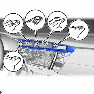
Disengage the 4 clips and 9 guides and remove the instrument cluster finish panel assembly as shown in the illustration.
-
-
REMOVE COMBINATION METER ASSEMBLY
-
DISCONNECT FRONT DOOR OPENING TRIM WEATHERSTRIP LH
-
Disconnect the front door opening trim weatherstrip LH.
-
-
REMOVE FRONT PILLAR GARNISH LH
-
REMOVE INSTRUMENT SIDE PANEL LH
-
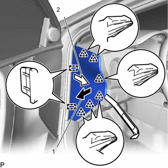
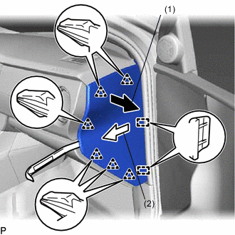
Using a moulding remover, disengage the 6 clips in the direction indicated by the arrow (1).
-
Pull the instrument side panel LH in the direction indicated by the arrow (2) to disengage the 2 guides and remove the instrument side panel LH.
-
-
REMOVE UPPER INSTRUMENT CLUSTER FINISH PANEL SUB-ASSEMBLY
-
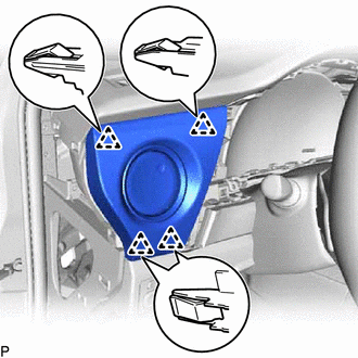
Disengage the 4 clips and remove the upper instrument cluster finish panel sub-assembly.
-
-
REMOVE CENTER INSTRUMENT CLUSTER FINISH PANEL
-
Using a moulding remover, disengage the claw and clip.
-
Using a moulding remover, disengage the 3 claws and 2 clips and remove the center instrument cluster finish panel.
-
-
DISCONNECT FRONT DOOR OPENING TRIM WEATHERSTRIP RH
-
Disconnect the front door opening trim weatherstrip RH.
-
-
REMOVE FRONT PILLAR GARNISH RH
Tech Tips
Use the same procedure as for the LH side.
-
REMOVE INSTRUMENT SIDE PANEL RH
-
Using a moulding remover, disengage the 6 clips in the direction indicated by the arrow (1).
-
Pull the instrument side panel RH in the direction indicated by the arrow (2) to disengage the 2 guides and remove the instrument side panel RH.
-
-
REMOVE INSTRUMENT CLUSTER FINISH PANEL GARNISH ASSEMBLY
-
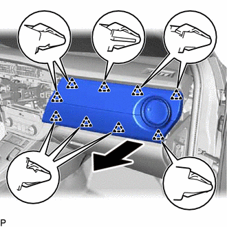
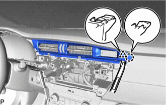
Disengage the 9 clips and remove the instrument cluster finish panel garnish assembly as shown in the illustration.
-
-
DISCONNECT NO. 2 INSTRUMENT PANEL WIRE
-
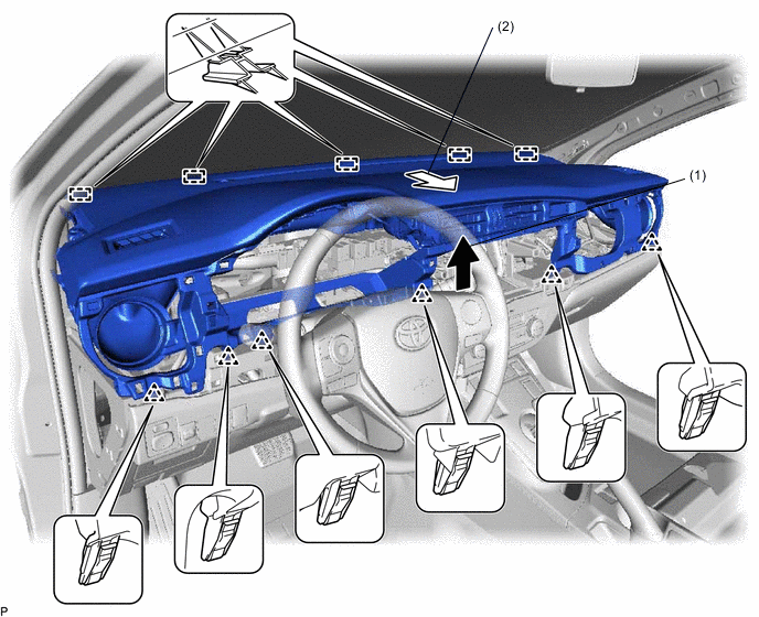
REMOVE UPPER INSTRUMENT PANEL ASSEMBLY
-
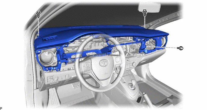
Remove the bolt <A> and 2 clips.
-
Pull the upper instrument panel assembly in the direction indicated by the arrow (1) to disengage the 6 clips.
-
Pull the upper instrument panel assembly in the direction indicated by the arrow (2) to disengage the 5 guides and remove the upper instrument panel assembly.
-