ROOM TEMPERATURE SENSOR REMOVAL
PROCEDURE
-
PRECAUTION
Note
After turning the power switch off, waiting time may be required before disconnecting the cable from the auxiliary battery negative (-) terminal. Therefore, make sure to read the disconnecting the cable from the auxiliary battery negative (-) terminal notices before proceeding with work.
-
REMOVE BATTERY BOX COVER (for LHD)
-
DISCONNECT CABLE FROM AUXILIARY BATTERY NEGATIVE TERMINAL (for LHD)
Note
When disconnecting the cable, some systems need to be initialized after the cable is reconnected.
-
REMOVE LOWER NO. 2 INSTRUMENT PANEL FINISH PANEL
-
REMOVE CENTER INSTRUMENT CLUSTER FINISH PANEL SUB-ASSEMBLY
-
REMOVE NO. 1 METER HOOD CLUSTER
-
REMOVE INSTRUMENT CLUSTER FINISH PANEL ASSEMBLY
-
REMOVE NO. 1 SWITCH HOLE BASE (for LHD)
-
REMOVE NO. 1 SWITCH HOLE BASE (for RHD)
-
REMOVE COOLER (ROOM TEMP. SENSOR) THERMISTOR
-
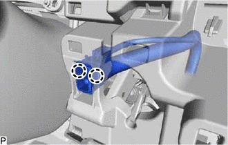
Disengage the 2 claws.
-
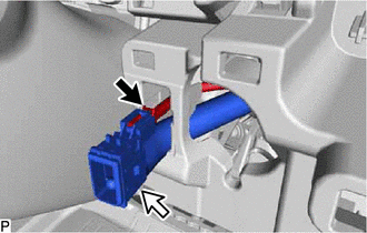
Disconnect the connector and aspirator to remove the cooler (room temp. sensor) thermistor.
-