KNEE AIRBAG ASSEMBLY REMOVAL

PROCEDURE
-
PRECAUTION
Note
After turning the power switch off, waiting time may be required before disconnecting the cable from the negative (-) auxiliary battery terminal. Therefore, make sure to read the disconnecting the cable from the negative (-) auxiliary battery terminal notices before proceeding with work.
-
REMOVE BATTERY BOX COVER
-
DISCONNECT CABLE FROM AUXILIARY BATTERY NEGATIVE TERMINAL
CAUTION:
Wait at least 90 seconds after disconnecting the cable from the negative (-) auxiliary battery terminal to disable the SRS system.
Note
When disconnecting the cable, some systems need to be initialized after the cable is reconnected.
-
REMOVE LOWER NO. 2 INSTRUMENT PANEL FINISH PANEL
-
REMOVE CENTER INSTRUMENT CLUSTER FINISH PANEL SUB-ASSEMBLY
-
REMOVE NO. 1 METER HOOD CLUSTER
-
REMOVE INSTRUMENT CLUSTER FINISH PANEL ASSEMBLY
-
REMOVE LOWER INSTRUMENT CLUSTER FINISH PANEL ASSEMBLY
-
REMOVE NO. 1 SWITCH HOLE BASE (for LHD)
-
REMOVE NO. 1 SWITCH HOLE BASE (for RHD)
-
REMOVE NO. 1 INSTRUMENT PANEL UNDER COVER SUB-ASSEMBLY (w/ Instrument Panel Under Cover)
-
REMOVE LOWER NO. 1 INSTRUMENT PANEL AIRBAG ASSEMBLY
CAUTION:
When storing the lower No. 1 instrument panel airbag assembly, keep the airbag deployment side facing upward.
-
Check that the power switch is off.
-
Check that the cable is disconnected from the negative (-) auxiliary battery terminal.
CAUTION:
Wait at least 90 seconds after disconnecting the cable from the negative (-) auxiliary battery terminal to disable the SRS system.
-
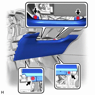
Remove the 4 bolts.
-
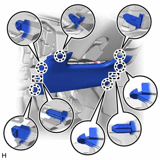
Disengage the 6 claws and 2 guides to separate the lower No. 1 instrument panel airbag assembly.
Note
When removing the lower No. 1 instrument panel airbag assembly, do not pull the airbag wire harness.
-
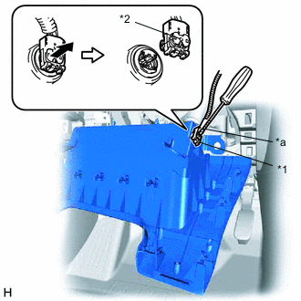
*1 Airbag Connector *2 Airbag Connector Lock *a Protective Tape Using a screwdriver with its tip wrapped with protective tape, release the airbag connector lock.
-
Disconnect the airbag connector to remove the lower No. 1 instrument panel airbag assembly.
Note
When disconnecting any airbag connector, take care not to damage the airbag wire harness.
-