THEFT DETERRENT SYSTEM Glass Breakage Sensor Circuit
DESCRIPTION
When the main body ECU (multiplex network body ECU) detects that the glass breakage sensor (back door glass) is broken, the theft deterrent system switches from the armed state to the alarm sounding state.
WIRING DIAGRAM
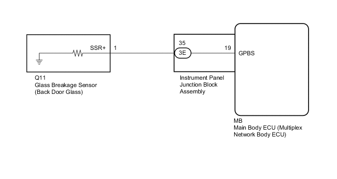
| *a | Instrument Panel Junction Block Assembly |
| *b | Glass Breakage Sensor (Back Door Glass) |
| *c | Main Body ECU (Multiplex Network Body ECU) |
PROCEDURE
-
READ VALUE USING GTS (SEALED GLAS BRAK SEN)
-
Connect the GTS to the DLC3.
-
Turn the power switch on (IG).
-
Turn the GTS on.
-
Enter the following menus: Body Electrical / Main Body / Data List.
-
According to the display on the GTS, read the Data List.
Body Electrical > Main Body > Data ListTester Display Measurement Item Range Normal Condition Diagnostic Note Sealed Glas Brak Sen Glass breakage sensor connection With or Without With: Glass breakage sensor connected
Without: Glass breakage sensor not connected
-
Body Electrical > Main Body > Data ListTester Display Sealed Glas Brak Sen OK With appears on the tester screen. Result Proceed to OK NG
OK 
REPLACE MAIN BODY ECU (MULTIPLEX NETWORK BODY ECU) Click here
NG 
-
-
INSPECT GLASS BREAKAGE SENSOR (BACK DOOR GLASS)
-
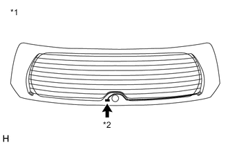
*1 Back Door Glass *2 Connector Disconnect the Q11 glass breakage sensor (back door glass) connector.
-
Measure the resistance according to the value(s) in the table below.
Standard Resistance Tester Connection Condition Specified Condition 1 - Body ground Always Below 1 Ω Result Proceed to OK NG
NG
REPLACE GLASS BREAKAGE SENSOR (BACK DOOR GLASS)
OK
-
-
INSPECT INSTRUMENT PANEL JUNCTION BLOCK ASSEMBLY
-
Remove the main body ECU (multiplex network body ECU).
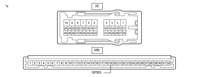
*a Component without harness connected
(Instrument Panel Junction Block Assembly)
- - -
Disconnect the 3E instrument panel junction block assembly connector.
-
Measure the resistance according to the value(s) in the table below.
Standard Resistance Tester Connection Condition Specified Condition 3E-35 - MB-19 (GPBS) Always Below 1 Ω Result Proceed to OK NG
NG
REPLACE INSTRUMENT PANEL JUNCTION BLOCK ASSEMBLY Click here
OK
-
-
CHECK HARNESS AND CONNECTOR (INSTRUMENT PANEL JUNCTION BLOCK ASSEMBLY - GLASS BREAKAGE SENSOR (BACK DOOR GLASS))
-
Measure the resistance according to the value(s) in the table below.
Standard Resistance Tester Connection Condition Specified Condition 3E-35 - Q11-1 (SSR+) Always Below 1 Ω 3E-35 - Body ground Always 10 kΩ or higher Q11-1 (SSR+) - Body ground Always 10 kΩ or higher Result Proceed to OK NG
OK
REPLACE MAIN BODY ECU (MULTIPLEX NETWORK BODY ECU) Click here
NG
REPAIR OR REPLACE HARNESS OR CONNECTOR
-