ENTRY AND START SYSTEM(for Start Function) TERMINALS OF ECU
-
CHECK CERTIFICATION ECU (SMART KEY ECU ASSEMBLY)
-
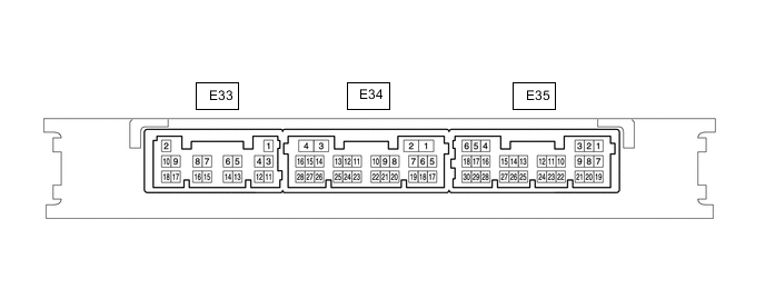
Disconnect the E33 and E35 certification ECU (smart key ECU assembly) connectors.
-
Measure the voltage and resistance according to the value(s) in the table below.
Tech Tips
Measure the values on the wire harness side with the connector disconnected.
Tester Connection Input/Output Wiring Color Terminal Description Condition Specified Condition Related Data List Item E33-9 (IG2D) - Body ground Output GR - Body ground IG2 signal 20°C (68°F) Approximately 310.14 Ω IG2 Relay Monitor(Outside) E33-18 (STP1) - Body ground Input L - Body ground Stop light switch signal Brake pedal depressed → Brake pedal released 9 V or higher → 1 V or less Stop Light Switch1 E33-2 (+B) - Body ground Input W - Body ground Power source Power switch off 11 to 14 V - E33-11 (E) - Body ground - W-B - Body ground Ground Always Below 1 Ω - E35-30 (SSW2) - Body ground Input B - Body ground SSW2 contact signal
Tech Tips
Backup for SSW1. Behaves the same way as SSW1.
Power switch pushed → Power switch not pushed Below 1 Ω → 10 kΩ or higher Start Switch2 E35-28 (SSW1) - Body ground Input SB - Body ground SSW1 contact signal Power switch pushed → Power switch not pushed Below 1 Ω → 10 kΩ or higher Start Switch1 E35-6 (IG1D) - Body ground Output W - Body ground IG1 signal 20°C (68°F) 54.32 to 79.32 Ω IG1 Relay Monitor(Outside) E35-4 (ACCD) - Body ground Output V - Body ground ACC signal 20°C (68°F) 163 to 238 Ω ACC Relay Monitor E35-27 (SPD) - E33-11 (E) Input V - W-B Vehicle speed signal Always 30 kΩ or higher Vehicle Speed Signal E35-25 (PPOS) - Body ground Input SB - Body ground P position signal Always 30 kΩ or higher - -
Reconnect the E33 and E35 certification ECU (smart key ECU assembly) connectors.
-
Measure the voltage and check for pulses according to the value(s) in the table below.
Tester Connection Input/Output Wiring Color Terminal Description Condition Specified Condition Related Data List Item E33-9 (IG2D) - E33-11 (E) Output GR - W-B IG2 signal Power switch on (ACC) → Power switch on (IG) 1 V or less → 9 V or higher - E35-30 (SSW2) - E33-11 (E) Input B - W-B SSW2 contact signal
Tech Tips
Backup for SSW1. Behaves the same way as SSW1.
Power switch not pushed → Power switch pushed 9 V or higher → 1 V or less Start Switch2 E35-28 (SSW1) - E33-11 (E) Input SB - W-B SSW1 contact signal Power switch not pushed → Power switch pushed 9 V or higher → 1 V or less Start Switch1 E35-4 (ACCD) - E33-11 (E) Output V - W-B ACC signal Power switch off → Power switch on (ACC) 1 V or less → 8.5 V or higher ACC Relay Monitor E35-6 (IG1D) - E33-11 (E) Output W - W-B IG1 signal Power switch on (ACC) → Power switch on (IG) 1 V or less → 9 V or higher IG1 Relay Monitor(Outside) E33-7 (ST2) - Body ground Output V - Body ground Starting control signal
-
P position signal
-
With the brake pedal depressed, the power switch is pressed and held → After approx. 3 sec. has elapsed, the power switch is released
9 V or higher → 1 V or less - E35-27 (SPD) - E33-11 (E) Input V - W-B Vehicle speed signal Vehicle being driven at approx. 5 km/h (3 mph) Pulse generation
(See waveform 2)
Vehicle Speed Signal E35-25 (PPOS) - E33-11 (E) Input SB - W-B P position signal
-
P position signal
-
Power switch on (ACC) → Power switch on (IG)
Pulse generation
(See waveform 1)
- -
-
Using an oscilloscope, check the waveform of the ECU.
-
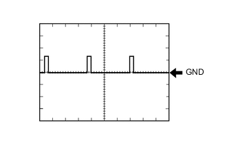
Waveform 1
Item Content Tester Connection E35-25 (PPOS) - E33-11 (E) Tool Setting 10 V/DIV., 10 ms/DIV. Condition Power switch on (IG), P position -
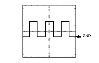
Waveform 2
Item Content Tester Connection E35-27 (SPD) - E33-11 (E) Tool Setting 5 V/DIV., 100 ms./DIV. Condition Power switch on (READY), vehicle being driven at approx. 5 km/h (3 mph) Tech Tips
The wavelength becomes shorter as the vehicle speed increases.
-
-
-
CHECK HYBRID VEHICLE CONTROL ECU ASSEMBLY