ENTRY AND START SYSTEM(for Entry Function) SYSTEM DIAGRAM
-
This is a detailed diagram related to the certification ECU (smart key ECU assembly).
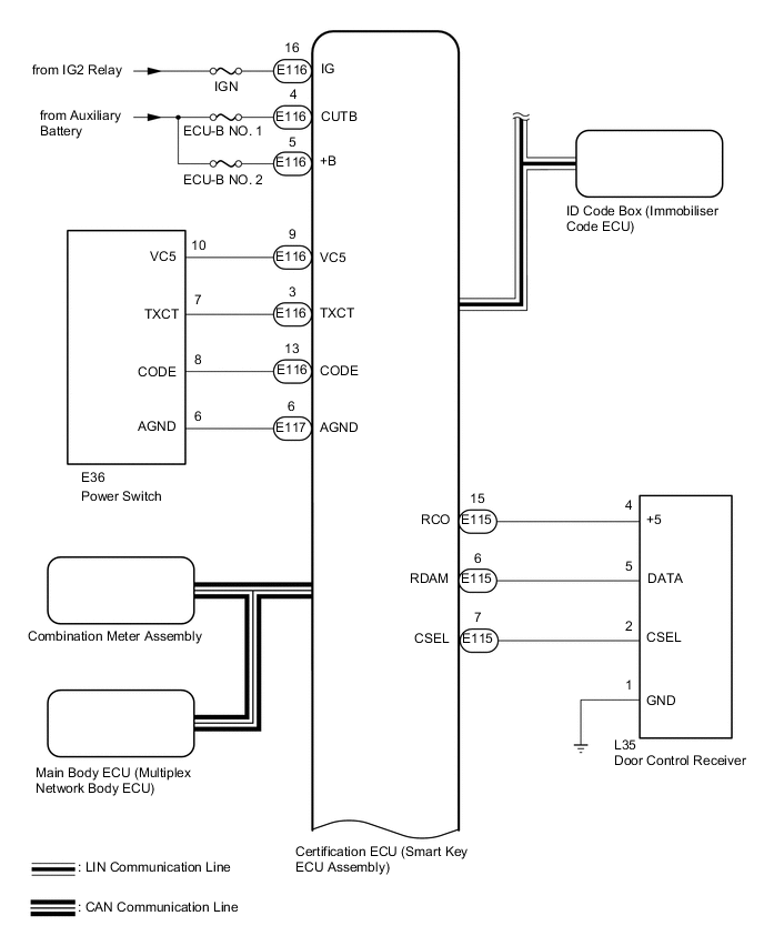
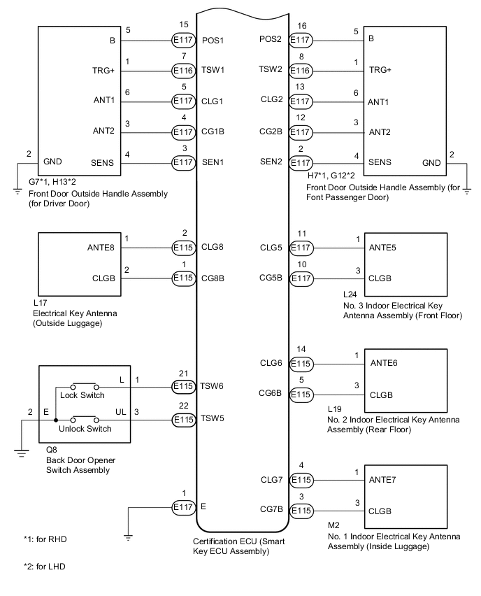
-
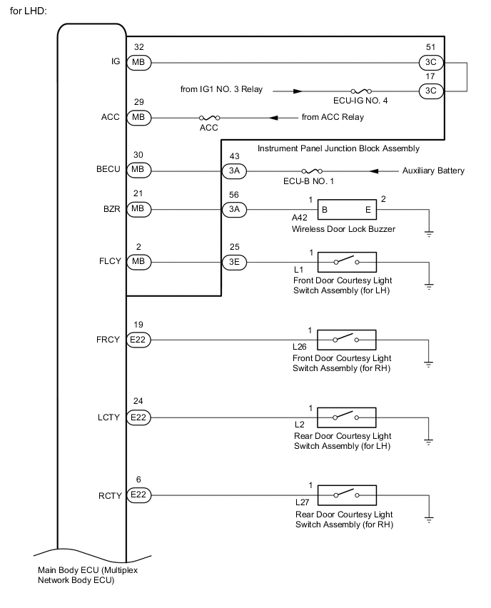
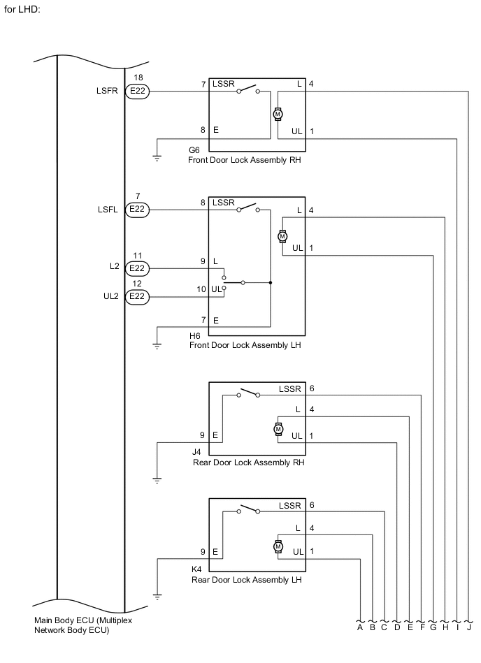
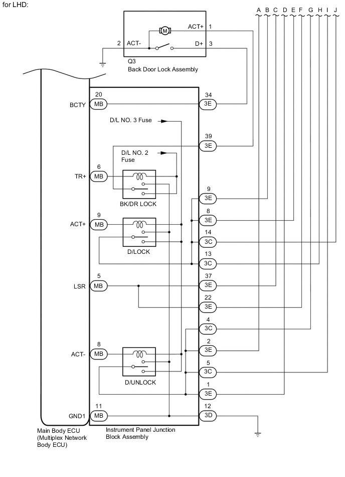
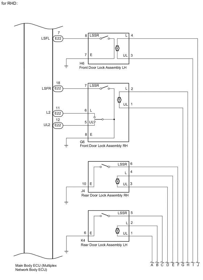
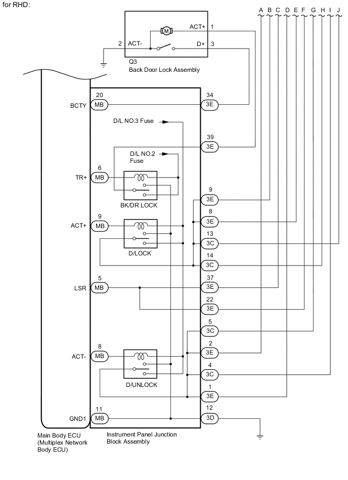
This is a detailed diagram related to the main body ECU (multiplex network body ECU).
| Component | Function |
|---|---|
| Front door outside handle assembly | Receives request signals from the certification ECU (smart key ECU assembly) via the built-in electrical key antenna (front door) and forms the vehicle exterior detection area. Uses the built-in touch sensor (lock sensor/unlock sensor) to detect the operation of the front door outside handle assembly and sends signals to the certification ECU (smart key ECU assembly). |
| No. 3 indoor electrical key antenna assembly (front floor) No. 2 indoor electrical key antenna assembly (rear floor) No. 1 indoor electrical key antenna assembly (inside luggage) |
Receives the request code from the certification ECU (smart key ECU assembly) and forms the vehicle interior detection area. |
| Electrical key antenna (outside luggage) | Receives the request code from the certification ECU (smart key ECU assembly) and forms the back door exterior detection area. |
| Back door opener switch assembly | Sends switch operation signals to the certification ECU (smart key ECU assembly). |
| Door control receiver | Receives the entry and start system code/wireless code sent from the electrical key transmitter sub-assembly and sends it to the certification ECU (smart key ECU assembly). |
| Wireless door lock buzzer | Sounds when warning functions operate in accordance with certification ECU (smart key ECU assembly) control. |
| Electrical key transmitter sub-assembly | Sends the ID code upon receiving a request signal. |
| Certification ECU (smart key ECU assembly) | Sends request codes to each electrical key antenna. Distinguishes and verifies the ID code from the electrical key transmitter sub-assembly and sends signals to each ECU in response to operated functions (controls entire system). Performs encryption code communication with the ID code box (immobiliser code ECU) when ignition operations are performed. |