CAN COMMUNICATION SYSTEM SYSTEM DIAGRAM
-
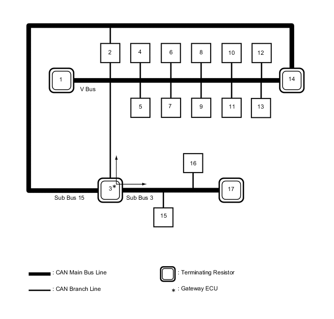
OVERALL CAN BUS DIAGRAM
-
The CAN communication system is composed of 3 buses.
1 Combination Meter Assembly
(for V Bus)
2 Skid Control ECU (Brake Booster with Master Cylinder Assembly)
(for V Bus and Sub Bus 15)
3 Hybrid Vehicle Control ECU Assembly
(for V Bus, Sub Bus 3 and Sub Bus 15)
4 Air Conditioning Amplifier Assembly
(for V Bus)
5 Radio and Display Receiver Assembly
(for Radio and Display Type)
(for V Bus)
6 Certification ECU (Smart Key ECU Assembly)
(for V Bus)
7 Power Steering ECU Assembly
(for V Bus)
8 Airbag Sensor Assembly
(for V Bus)
9 Transmission Control ECU Assembly
(for V Bus)
10 Steering Sensor (Spiral Cable with Sensor Sub-assembly)
(for V Bus)
11 DLC3
(for V Bus)
12 Main Body ECU (Multiplex Network Body ECU)
(for V Bus)
13 Pre-crash Safety City Sensor
(w/ Toyota Safety Sense)
(for V Bus)
14 ECM
(for V Bus and Sub Bus 15)
15 Headlight Swivel ECU Assembly
(w/ Automatic Headlight Beam Level Control System)
(for Sub Bus 3)
16 Clearance Warning ECU Assembly
(w/ Simple Intelligent Parking Assist System)
(for Sub Bus 3)
17 No. 1 CAN Junction Terminal
(w/ Automatic Headlight Beam Level Control System or Simple Intelligent Parking Assist System)
(for Sub Bus 3)
- - Tech Tips
-
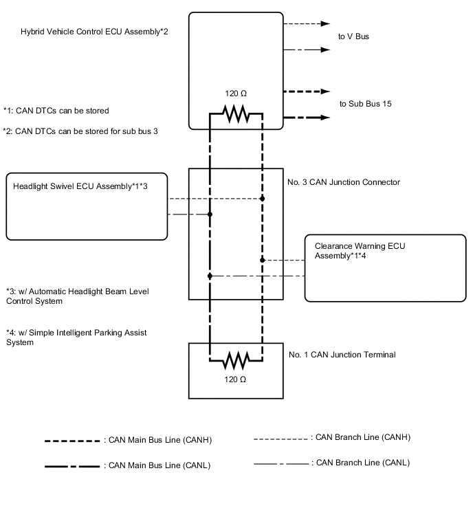
The hybrid vehicle control ECU assembly functions as a gateway between the V bus and sub bus 3.
-
Refer to the following bus wiring diagrams for details.
-
-
-
V BUS (for LHD)
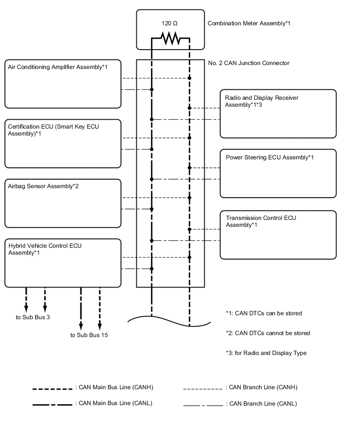
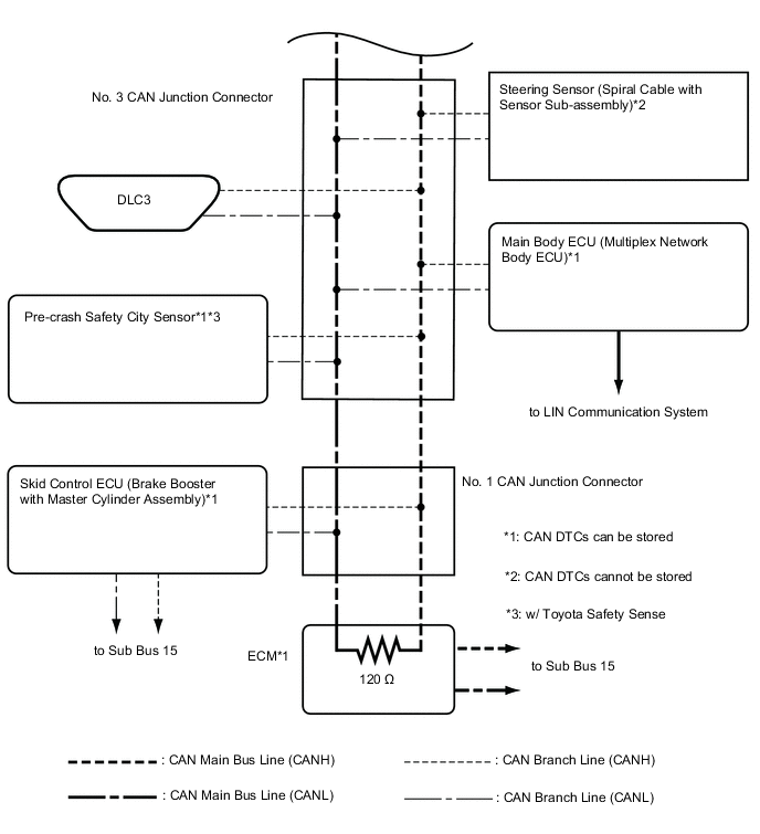
Tech Tips
The CAN communication system connects to other networks via ECUs that function as a gateway.
-
V BUS (for RHD)
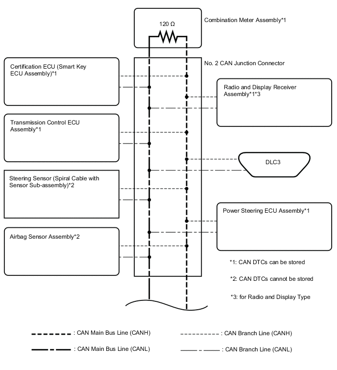
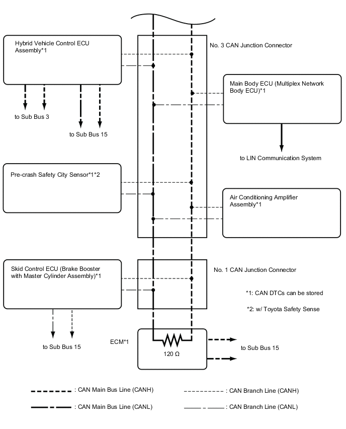
Tech Tips
The CAN communication system connects to other networks via ECUs that function as a gateway.
-
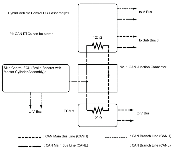
SUB BUS 3 (w/ Automatic Headlight Beam Level Control System or Simple Intelligent Parking Assist System)
-
SUB BUS 15