LIN COMMUNICATION SYSTEM, Diagnostic DTC:B2786
| DTC Code | DTC Name |
|---|---|
| B2786 | No Response from Steering Lock ECU |
DESCRIPTION
This DTC is stored when LIN communication between the certification ECU (smart key ECU assembly) and transmission control ECU assembly stops for 10 seconds or more.
| DTC No. | Detection Item | DTC Detection Condition | Trouble Area |
|---|---|---|---|
| B2786 | No Response from Steering Lock ECU | No communication between transmission control ECU assembly and certification ECU (smart key ECU assembly) for 10 seconds or more. |
|
WIRING DIAGRAM
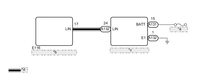
| *a | P CON MAIN |
| *b | Certification ECU (Smart Key ECU Assembly) |
| *c | Transmission Control ECU Assembly |
| *d | LIN Communication Line |
CAUTION / NOTICE / HINT
Note
-
Inspect the fuses for circuits related to this system before performing the following procedure.
-
If the certification ECU (smart key ECU assembly) or transmission control ECU assembly is replaced, refer to Service Bulletin.
PROCEDURE
-
CHECK DTC OUTPUT
-
Clear the DTCs.
Body Electrical > Entry&Start > Clear DTCs -
Recheck for DTCs.
Body Electrical > Entry&Start > Trouble CodesTech Tips
When DTC B2786 and B2785 are output simultaneously, perform troubleshooting for DTC B2785 first.
Result Result Proceed to Only B2786 is output A DTC B2786 and B2785 are output simultaneously B
B 
GO TO DTC B2785 Click here
A 
-
-
CHECK HARNESS AND CONNECTOR (TRANSMISSION CONTROL ECU ASSEMBLY - AUXILIARY BATTERY AND BODY GROUND)
-
Disconnect the A131 and A132 transmission control ECU assembly connectors.
-
Measure the voltage according to the value(s) in the table below.
Standard Voltage Tester Connection Condition Specified Condition A131-15 (BATT) - A132-1 (E1) Power switch off 11 to 14 V -
Measure the resistance according to the value(s) in the table below.
Standard Resistance Tester Connection Condition Specified Condition A132-1 (E1) - Body ground Always Below 1 Ω Result Proceed to OK NG
NG
REPAIR OR REPLACE HARNESS OR CONNECTOR
OK
-
-
CHECK HARNESS AND CONNECTOR (CERTIFICATION ECU (SMART KEY ECU ASSEMBLY) - TRANSMISSION CONTROL ECU ASSEMBLY)
-
Disconnect the E116 certification ECU (smart key ECU assembly) connector.
-
Measure the resistance according to the value(s) in the table below.
Standard Resistance Tester Connection Condition Specified Condition E116-17 (LIN) - A132-24 (LIN) Always Below 1 Ω E116-17 (LIN) - Body ground Always 10 kΩ or higher A132-24 (LIN) - Body ground Always 10 kΩ or higher Result Proceed to OK NG
NG
REPAIR OR REPLACE HARNESS OR CONNECTOR
OK
-
-
REPLACE TRANSMISSION CONTROL ECU ASSEMBLY
-
Replace the transmission control ECU assembly.
for LHD: Click here
for RHD: Click here
Result Proceed to NEXT
NEXT
-
-
CHECK DTC OUTPUT
-
Clear the DTCs.
Body Electrical > Entry&Start > Clear DTCs -
Recheck for DTCs.
Body Electrical > Entry&Start > Trouble CodesOK DTC B2786 is not output. Result Proceed to OK NG
OK
END (TRANSMISSION CONTROL ECU ASSEMBLY WAS DEFECTIVE)
NG
REPLACE CERTIFICATION ECU (SMART KEY ECU ASSEMBLY)
-