LIN COMMUNICATION SYSTEM TERMINALS OF ECU
-
CHECK INSTRUMENT PANEL JUNCTION BLOCK ASSEMBLY AND MAIN BODY ECU (MULTIPLEX NETWORK BODY ECU)
-
Disconnect the MB main body ECU (multiplex network body ECU) connector.
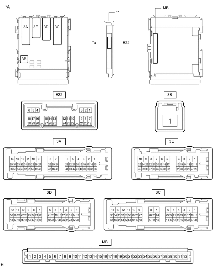
*A Main Body ECU (Multiplex Network Body ECU) with 1 Connector - - *1 Main Body ECU (Multiplex Network Body ECU) - - *a 1 Connector - - 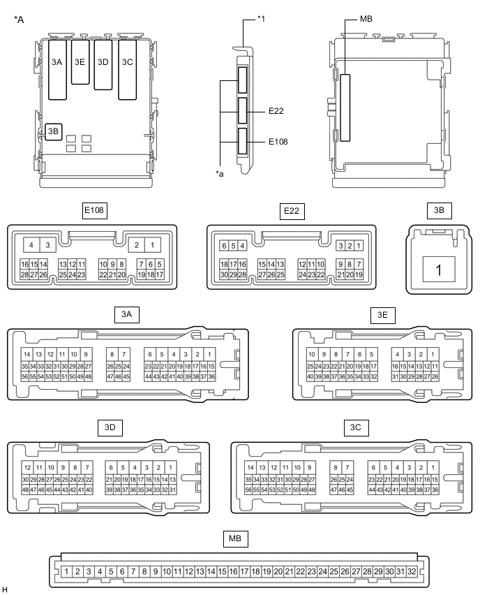
*A Main Body ECU (Multiplex Network Body ECU) with 3 Connectors - - *1 Main Body ECU (Multiplex Network Body ECU) - - *a 3 Connectors - - -
Measure the voltage and resistance according to the value(s) in the table below.
Tech Tips
Measure the values on the wire harness side with the connectors disconnected.
Tester Connection Wiring Color Terminal Description Condition Specified Condition MB-11 (GND1) - Body ground - Ground Always Below 1 Ω MB-30 (BECU) - Body ground - Auxiliary battery power supply Power switch off 11 to 14 V MB-29 (ACC) - Body ground - ACC power supply Power switch on (ACC) 11 to 14 V MB-29 (ACC) - Body ground - ACC power supply Power switch off Below 1 V MB-32 (IG) - Body ground - Power switch power supply Power switch on (IG) 11 to 14 V MB-32 (IG) - Body ground - Power switch power supply Power switch off Below 1 V If the result is not as specified, there may be a malfunction in the wire harness.
-
Reconnect the MB main body ECU (multiplex network body ECU) connector.
-
Check for pulses according to the value(s) in the table below.
Tester Connection Wiring Color Terminal Description Condition Specified Condition 3C-22 (LIN2) - Body ground GR - Body ground LIN communication line Power switch on (IG) Pulse generation 3C-23 (LIN2) - Body ground*1 V - Body ground LIN communication line Power switch on (IG) Pulse generation 3E-29 (LIN2) - Body ground*2 V - Body ground LIN communication line Power switch on (IG) Pulse generation 3E-14 (LIN2) - Body ground*2 V - Body ground LIN communication line Power switch on (IG) Pulse generation
-
*1: for Models with Jam Protection Function on Driver Door Window Only
-
*2: for Models with Jam Protection Function on 4 Windows
If the result is not as specified, the main body ECU (multiplex network body ECU) or instrument panel junction block assembly may be malfunctioning.
-
-
-
CHECK FRONT DOOR WINDOW REGULATOR ASSEMBLY (for Driver Door)
-
Disconnect the H14*1 or G5*2 front door window regulator assembly (for driver door) connector.
-
*1: for LHD
-
*2: for RHD

*A for LHD *B for RHD -
-
Measure the voltage and resistance according to the value(s) in the table below.
Tech Tips
Measure the values on the wire harness side with the connector disconnected.
for LHD Tester Connection Wiring Color Terminal Description Condition Specified Condition H14-2 (B) - Body ground GR - Body ground Auxiliary battery power supply Power switch off 11 to 14 V H14-1 (GND) - Body ground W-B - Body ground Ground Always Below 1 Ω for RHD Tester Connection Wiring Color Terminal Description Condition Specified Condition G5-2 (B) - Body ground GR - Body ground Auxiliary battery power supply Power switch off 11 to 14 V G5-1 (GND) - Body ground W-B - Body ground Ground Always Below 1 Ω If the result is not as specified, there may be a malfunction in the wire harness.
-
Reconnect the H14*1 or G5*2 front door window regulator assembly (for driver door) connector.
-
*1: for LHD
-
*2: for RHD
-
-
Check for pulses according to the value(s) in the table below.
for LHD Tester Connection Wiring Color Terminal Description Condition Specified Condition H14-9 (LIN) - Body ground V - Body ground LIN communication line Power switch on (IG) Pulse generation for RHD Tester Connection Wiring Color Terminal Description Condition Specified Condition G5-9 (LIN) - Body ground V - Body ground LIN communication line Power switch on (IG) Pulse generation If the result is not as specified, the front door window regulator assembly (for driver door) may be malfunctioning.
-
-
CHECK FRONT DOOR WINDOW REGULATOR ASSEMBLY (for Front Passenger Door) (for Models with Jam Protection Function on 4 Windows)
-
Disconnect the G13*1 or H4*2 front door window regulator assembly (for front passenger door) connector.
-
*1: for LHD
-
*2: for RHD

*A for LHD *B for RHD -
-
Measure the voltage and resistance according to the value(s) in the table below.
Tech Tips
Measure the values on the wire harness side with the connector disconnected.
for LHD Tester Connection Wiring Color Terminal Description Condition Specified Condition G13-2 (B) - Body ground GR - Body ground Auxiliary battery power supply Power switch off 11 to 14 V G13-1 (GND) - Body ground W-B - Body ground Ground Always Below 1 Ω for RHD Tester Connection Wiring Color Terminal Description Condition Specified Condition H4-2 (B) - Body ground GR - Body ground Auxiliary battery power supply Power switch off 11 to 14 V H4-1 (GND) - Body ground W-B - Body ground Ground Always Below 1 Ω If the result is not as specified, there may be a malfunction in the wire harness.
-
Reconnect the G13*1 or H4*2 front door window regulator assembly (for front passenger door) connector.
-
*1: for LHD
-
*2: for RHD
-
-
Check for pulses according to the value(s) in the table below.
for LHD Tester Connection Wiring Color Terminal Description Condition Specified Condition G13-9 (LIN) - Body ground GR - Body ground LIN communication line Power switch on (IG) Pulse generation for RHD Tester Connection Wiring Color Terminal Description Condition Specified Condition H4-9 (LIN) - Body ground GR - Body ground LIN communication line Power switch on (IG) Pulse generation If the result is not as specified, the front door window regulator assembly (for front passenger door) may be malfunctioning.
-
-
CHECK REAR DOOR WINDOW REGULATOR ASSEMBLY (for RH Door) (for Models with Jam Protection Function on 4 Windows)
-
Disconnect the J3 rear door window regulator assembly (for RH door) connector.

-
Measure the voltage and resistance according to the value(s) in the table below.
Tech Tips
Measure the values on the wire harness side with the connector disconnected.
Tester Connection Wiring Color Terminal Description Condition Specified Condition J3-2 (B) - Body ground LA-L - Body ground Auxiliary battery power supply Power switch off 11 to 14 V J3-1 (GND) - Body ground W-B - Body ground Ground Always Below 1 Ω If the result is not as specified, there may be a malfunction in the wire harness.
-
Reconnect the J3 rear door window regulator assembly (for RH door) connector.
-
Check for pulses according to the value(s) in the table below.
Tester Connection Wiring Color Terminal Description Condition Specified Condition J3-9 (LIN) - Body ground V - Body ground LIN communication line Power switch on (IG) Pulse generation If the result is not as specified, the rear door window regulator assembly (for RH door) may be malfunctioning.
-
-
CHECK REAR DOOR WINDOW REGULATOR ASSEMBLY (for LH Door) (for Models with Jam Protection Function on 4 Windows)
-
Disconnect the K3 rear door window regulator assembly (for LH door) connector.

-
Measure the voltage and resistance according to the value(s) in the table below.
Tech Tips
Measure the values on the wire harness side with the connector disconnected.
Tester Connection Wiring Color Terminal Description Condition Specified Condition K3-2 (B) - Body ground LA-P - Body ground Auxiliary battery power supply Power switch off 11 to 14 V K3-1 (GND) - Body ground W-B - Body ground Ground Always Below 1 Ω If the result is not as specified, there may be a malfunction in the wire harness.
-
Reconnect the K3 rear door window regulator assembly (for LH door) connector.
-
Check for pulses according to the value(s) in the table below.
Tester Connection Wiring Color Terminal Description Condition Specified Condition K3-9 (LIN) - Body ground V - Body ground LIN communication line Power switch on (IG) Pulse generation If the result is not as specified, the rear door window regulator assembly (for LH door) may be malfunctioning.
-
-
CHECK POWER WINDOW REGULATOR MASTER SWITCH ASSEMBLY (for Models with Jam Protection Function on 4 Windows)
-
Disconnect the H12*1 or G3*2 power window regulator master switch assembly connector.
-
*1: for LHD
-
*2: for RHD

*A for LHD *B for RHD -
-
Measure the voltage and resistance according to the value(s) in the table below.
Tech Tips
Measure the values on the wire harness side with the connector disconnected.
for LHD Tester Connection Wiring Color Terminal Description Condition Specified Condition H12-11 (B) - Body ground W - Body ground Auxiliary battery power supply Power switch off 11 to 14 V H12-12 (GND) - Body ground BR - Body ground Ground Always Below 1 Ω for RHD Tester Connection Wiring Color Terminal Description Condition Specified Condition G3-11 (B) - Body ground W - Body ground Auxiliary battery power supply Power switch off 11 to 14 V G3-12 (GND) - Body ground BR - Body ground Ground Always Below 1 Ω If the result is not as specified, there may be a malfunction in the wire harness.
-
Reconnect the H12*1 or G3*2 power window regulator master switch assembly connector.
-
*1: for LHD
-
*2: for RHD
-
-
Check for pulses according to the value(s) in the table below.
for LHD Tester Connection Wiring Color Terminal Description Condition Specified Condition H12-17 (LIN1) - Body ground GR - Body ground LIN communication line Power switch on (IG) Pulse generation H12-16 (LIN2) - Body ground V - Body ground LIN communication line Power switch on (IG) Pulse generation for RHD Tester Connection Wiring Color Terminal Description Condition Specified Condition G3-17 (LIN1) - Body ground GR - Body ground LIN communication line Power switch on (IG) Pulse generation G3-16 (LIN2) - Body ground V - Body ground LIN communication line Power switch on (IG) Pulse generation If the result is not as specified, the power window regulator master switch assembly may be malfunctioning.
-
-
CHECK CERTIFICATION ECU (SMART KEY ECU ASSEMBLY)
-
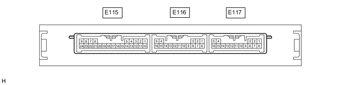
Disconnect the E116 and E117 certification ECU (smart key ECU assembly) connectors.
-
Measure the voltage and resistance according to the value(s) in the table below.
Tech Tips
Measure the values on the wire harness side with the connector disconnected.
Tester Connection Wiring Color Terminal Description Condition Specified Condition E117-1 (E) - Body ground W-B - Body ground Ground Always Below 1 Ω E116-5 (+B) - Body ground W - Body ground Auxiliary battery power supply Power switch off 11 to 14 V If the result is not as specified, there may be a malfunction in the wire harness.
-
Reconnect the E116 and E117 certification ECU (smart key ECU assembly) connectors.
-
Check for pulses according to the value(s) in the table below.
Tester Connection Wiring Color Terminal Description Condition Specified Condition E116-12 (LIN) - Body ground V - Body ground LIN communication line Power switch on (IG) Pulse generation If the result is not as specified, the certification ECU (smart key ECU assembly) may be malfunctioning.
-
-
CHECK POWER MANAGEMENT CONTROL ECU
-
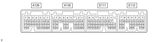
Disconnect the E111 and E112 power management control ECU connectors.
-
Measure the resistance and voltage according to the value(s) in the table below.
Terminal No. (Symbol) Wiring Color Terminal Description Condition Specified Condition E111-6 (E1) - Body ground BR - Body ground Ground Always Below 1 Ω E112-7 (AM21) - Body ground L - Body ground Auxiliary battery power supply Power switch off 11 to 14 V E111-1 (AM22) - Body ground L - Body ground Auxiliary battery power supply Power switch off 11 to 14 V If the result is not as specified, there may be a malfunction on the wire harness side.
-
Reconnect the E111 and E112 power management control ECU connectors.
-
Check for pulses according to the value(s) in the table below.
Tester Connection Wiring Color Terminal Description Condition Specified Condition E112-11 (LIN2) - Body ground V - Body ground LIN communication line Power switch on (IG) Pulse generation If the result is not as specified, the power management control ECU may be malfunctioning.
-
-
CHECK TRANSMISSION CONTROL ECU ASSEMBLY
-
Disconnect the A131 and A132 transmission control ECU assembly connectors.

-
Measure the resistance and voltage according to the value(s) in the table below.
Terminal No. (Symbol) Wiring Color Terminal Description Condition Specified Condition A132-1 (E1) - Body ground W-B - Body ground Ground Always Below 1 Ω A131-15 (BATT) - Body ground W - Body ground Auxiliary battery power supply Power switch off 11 to 14 V If the result is not as specified, there may be a malfunction on the wire harness side.
-
Reconnect the A131 and A132 transmission control ECU assembly connectors.
-
Check for pulses according to the value(s) in the table below.
Tester Connection Wiring Color Terminal Description Condition Specified Condition A132-24 (LIN) - Body ground V - Body ground LIN communication line Power switch on (IG) Pulse generation If the result is not as specified, the transmission control ECU assembly may be malfunctioning.
-
-
CHECK ID CODE BOX (IMMOBILISER CODE ECU)
-
Disconnect the E87 ID code box (immobiliser code ECU) connector.

-
Measure the voltage and resistance according to the value(s) in the table below.
Tech Tips
Measure the values on the wire harness side with the connector disconnected.
Tester Connection Wiring Color Terminal Description Condition Specified Condition E87-5 (GND) - Body ground BR - Body ground Ground Always Below 1 Ω E87-1 (+B) - Body ground W - Body ground Auxiliary battery power supply Power switch off 11 to 14 V If the result is not as specified, there may be a malfunction in the wire harness.
-
Reconnect the E87 ID code box (immobiliser code ECU) connector.
-
Check for pulses according to the value(s) in the table below.
Tester Connection Wiring Color Terminal Description Condition Specified Condition E87-2 (LIN1) - Body ground V - Body ground LIN communication line Power switch on (IG) Pulse generation If the result is not as specified, the ID code box (immobiliser code ECU) may be malfunctioning.
-
-
CHECK DOUBLE LOCK DOOR CONTROL RELAY ASSEMBLY (w/ Double Locking System)
-
Disconnect the E107 double lock door control relay assembly connector.

-
Measure the resistance and voltage according to the value(s) in the table below.
Tech Tips
Measure the values on the wire harness side with the connector disconnected.
Tester Connection Wiring Color Terminal Description Condition Specified Condition E107-1 (+B) - Body ground B - Body ground Auxiliary battery power supply Power switch off 11 to 14 V E107-7 (CPUB) - Body ground LG - Body ground Auxiliary battery power supply Power switch off 11 to 14 V E107-14 (GND) - Body ground W-B - Body ground Ground Always Below 1 Ω If the result is not as specified, there may be a malfunction in the wire harness.
-
Reconnect the E107 double lock door control relay assembly connector.
-
Check for pulses according to the value(s) in the table below.
Tester Connection Wiring Color Terminal Description Condition Specified Condition E107-9 (MPX1) - Body ground GR - Body ground LIN communication line Double lock unset Pulse generation If the result is not as specified, the double lock door control relay assembly may be malfunctioning.
-
-
CHECK ROOF SUNSHADE ECU (SLIDING ROOF DRIVE GEAR ASSEMBLY) (w/ Roof Sunshade System)
-
Disconnect the a1 roof sunshade ECU (sliding roof drive gear assembly) connector.

-
Measure the resistance and voltage according to the value(s) in the table below.
Tech Tips
Measure the values on the wire harness side with the connector disconnected.
Tester Connection Wiring Color Terminal Description Condition Specified Condition a1-8 (B) - Body ground R-W - Body ground Auxiliary battery power supply Power switch off 11 to 14 V a1-12 (E) - Body ground B-W - Body ground Ground Always Below 1 Ω If the result is not as specified, there may be a malfunction in the wire harness.
-
Reconnect the a1 roof sunshade ECU (sliding roof drive gear assembly) connector.
-
Measure the voltage according to the value(s) in the table below.
Tester Connection Wiring Color Terminal Description Condition Specified Condition a1-11 (LIN) - Body ground B - Body ground LIN communication line Power switch on (IG) Pulse generation If the result is not as specified, the roof sunshade ECU (sliding roof drive gear assembly) may be malfunctioning.
-