SIMPLE INTELLIGENT PARKING ASSIST SYSTEM Main Switch Circuit
DESCRIPTION
When the IPA main switch assembly is turned on, a signal is sent to the clearance warning ECU assembly. The simple intelligent parking assist system operates according to this signal.
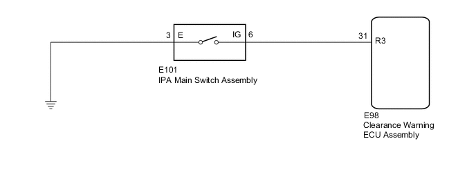
WIRING DIAGRAM
PROCEDURE
-
INSPECT IPA MAIN SWITCH ASSEMBLY
-
Remove the IPA main switch assembly.
-
Inspect the IPA main switch assembly.
OK IPA main switch assembly is normal. Result Proceed to OK NG
NG 
REPLACE IPA MAIN SWITCH ASSEMBLY Click here
OK 
-
-
CHECK HARNESS AND CONNECTOR (IPA MAIN SWITCH ASSEMBLY - CLEARANCE WARNING ECU ASSEMBLY AND BODY GROUND)
-
Disconnect the E101 IPA main switch assembly connector.
-
Disconnect the E98 clearance warning ECU assembly connector.
-
Measure the resistance according to the value(s) in the table below.
Standard Resistance Tester Connection Condition Specified Condition E101-6 (IG) - E98-31 (R3) Always Below 1 Ω E101-6 (IG) - Body ground Always 10 kΩ or higher E101-3 (E) - Body ground Always Below 1 Ω Result Proceed to OK NG
OK
PROCEED TO NEXT SUSPECTED AREA SHOWN IN PROBLEM SYMPTOMS TABLE Click here
NG
REPAIR OR REPLACE HARNESS OR CONNECTOR
-