TOYOTA PARKING ASSIST-SENSOR SYSTEM(for Hatchback), Diagnostic DTC:C1AEC
| DTC Code | DTC Name |
|---|---|
| C1AEC | Front Sensor Communication Malfunction |
DESCRIPTION
This DTC is stored when there is a short circuit in the communication line between the front sensors and the ECU, or when there is a malfunction in a front sensor.
| DTC No. | Detection Item | DTC Detection Condition | Trouble Area |
|---|---|---|---|
| C1AEC | Front Sensor Communication Malfunction | A short circuit in the communication line between the front sensors and ECU or a malfunction in a front sensor during initialization mode after the power switch is turned on (IG). |
|
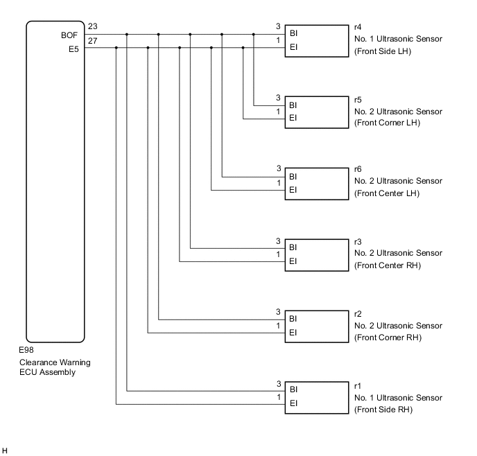
WIRING DIAGRAM
CAUTION / NOTICE / HINT
Note
-
If DTCs are output after repairs, turn the power switch on (IG) and turn the back sonar or clearance sonar switch assembly on. Then clear the DTCs.
-
Depending on the parts that are replaced during vehicle inspection or maintenance, performing initialization may be needed. Refer to Initialization.
PROCEDURE
-
CHECK HARNESS AND CONNECTOR (CLEARANCE WARNING ECU ASSEMBLY - ULTRASONIC SENSOR (FRONT SONARS))
-
Disconnect the E98 clearance warning ECU assembly connector.
-
Disconnect the r4 No. 1 ultrasonic sensor (front side LH) connector.
-
Disconnect the r5 No. 2 ultrasonic sensor (front corner LH) connector.
-
Disconnect the r6 No. 2 ultrasonic sensor (front center LH) connector.
-
Disconnect the r3 No. 2 ultrasonic sensor (front center RH) connector.
-
Disconnect the r2 No. 2 ultrasonic sensor (front corner RH) connector.
-
Disconnect the r1 No. 1 ultrasonic sensor (front side RH) connector.
-
Measure the resistance according to the value(s) in the table below.
Standard Resistance Tester Connection Condition Specified Condition E98-23 (BOF) - Body ground Always 10 kΩ or higher E98-23 (BOF) - E98-27 (E5) Always 10 kΩ or higher Result Proceed to OK NG
NG 
REPAIR OR REPLACE HARNESS OR CONNECTOR
OK 
-
-
INSPECT NO. 1 ULTRASONIC SENSOR (FRONT SIDE LH)
-
Remove the No. 1 ultrasonic sensor (front side LH).
-
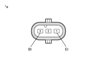
*a Component without harness connected
(No. 1 Ultrasonic Sensor (Front Side LH))
Measure the resistance according to the value(s) in the table below.
Standard Resistance Tester Connection Condition Specified Condition 3 (BI) - 1 (EI) Always 10 kΩ or higher Result Proceed to OK NG
NG
REPLACE NO. 1 ULTRASONIC SENSOR (FRONT SIDE LH) Click here
OK
-
-
INSPECT NO. 2 ULTRASONIC SENSOR (FRONT CORNER LH)
-
Remove the No. 2 ultrasonic sensor (front corner LH).
-
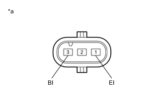
*a Component without harness connected
(No. 2 Ultrasonic Sensor (Front Corner LH))
Measure the resistance according to the value(s) in the table below.
Standard Resistance Tester Connection Condition Specified Condition 3 (BI) - 1 (EI) Always 10 kΩ or higher Result Proceed to OK NG
NG
REPLACE No. 2 ULTRASONIC SENSOR (FRONT CORNER LH) Click here
OK
-
-
INSPECT NO. 2 ULTRASONIC SENSOR (FRONT CENTER LH)
-
Remove the No. 2 ultrasonic sensor (front center LH).
-
*a Component without harness connected
(No. 2 Ultrasonic Sensor (Front Center LH))
Measure the resistance according to the value(s) in the table below.
Standard Resistance Tester Connection Condition Specified Condition 3 (BI) - 1 (EI) Always 10 kΩ or higher Result Proceed to OK NG
NG
REPLACE NO. 2 ULTRASONIC SENSOR (FRONT CENTER LH) Click here
OK
-
-
INSPECT NO. 2 ULTRASONIC SENSOR (FRONT CENTER RH)
-
Remove the No. 2 ultrasonic sensor (front center RH).
-
*a Component without harness connected
(No. 2 Ultrasonic Sensor (Front Center RH))
Measure the resistance according to the value(s) in the table below.
Standard Resistance Tester Connection Condition Specified Condition 3 (BI) - 1 (EI) Always 10 kΩ or higher Result Proceed to OK NG
NG
REPLACE NO. 2 ULTRASONIC SENSOR (FRONT CENTER RH) Click here
OK
-
-
INSPECT NO. 2 ULTRASONIC SENSOR (FRONT CORNER RH)
-
Remove the No. 2 ultrasonic sensor (front corner RH).
-
*a Component without harness connected
(No. 2 Ultrasonic Sensor (Front Corner RH))
Measure the resistance according to the value(s) in the table below.
Standard Resistance Tester Connection Condition Specified Condition 3 (BI) - 1 (EI) Always 10 kΩ or higher Result Proceed to OK NG
NG
REPLACE NO. 2 ULTRASONIC SENSOR (FRONT CORNER RH) Click here
OK
-
-
INSPECT NO. 1 ULTRASONIC SENSOR (FRONT SIDE RH)
-
Remove the No. 1 ultrasonic sensor (front side RH).
-
*a Component without harness connected
(No. 1 Ultrasonic Sensor (Front Side RH))
Measure the resistance according to the value(s) in the table below.
Standard Resistance Tester Connection Condition Specified Condition 3 (BI) - 1 (EI) Always 10 kΩ or higher Result Proceed to OK NG
OK
REPLACE CLEARANCE WARNING ECU ASSEMBLY for LHD: Click here
REPLACE CLEARANCE WARNING ECU ASSEMBLY for RHD: Click hereNG
REPLACE NO. 1 ULTRASONIC SENSOR (FRONT SIDE RH) Click here
-