STEERING COLUMN ASSEMBLY INSTALLATION

PROCEDURE
-
INSPECT STEERING COLUMN ASSEMBLY
-
INSTALL STEERING COLUMN ASSEMBLY
-
Install the steering column assembly with the bolt and 2 nuts.
- Torque:
- Bolt
- 36 N*m { 367 kgf*cm, 27 ft.*lbf }
- Nut
- 25 N*m { 255 kgf*cm, 18 ft.*lbf }
Note
Make sure that the wire harness is not interfering with the steering column assembly.
-
Connect each connector and engage each wire harness clamp to the steering column assembly.
-
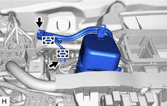
Engage the 2 wire harness clamps.
-
Connect the 2 connectors.
-
-
INSTALL LOWER NO. 1 INSTRUMENT PANEL AIRBAG ASSEMBLY
-
INSTALL UPPER INSTRUMENT PANEL ASSEMBLY
-
INSTALL BRAKE PEDAL SUPPORT ASSEMBLY
-
for LHD: Click here
-
for RHD: Click here
-
-
INSTALL NO. 2 STEERING INTERMEDIATE SHAFT ASSEMBLY
-
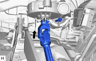
*a Matchmark Align the matchmarks on the No. 2 steering intermediate shaft assembly and steering column assembly.
-
Install the No. 2 steering intermediate shaft assembly to the steering column assembly.
-
Install the bolt.
- Torque:
- 35 N*m { 357 kgf*cm, 26 ft.*lbf }
-
-
CONNECT NO. 2 STEERING INTERMEDIATE SHAFT ASSEMBLY
-
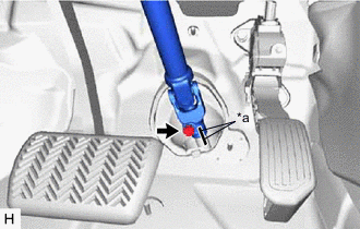
*a Matchmark Align the matchmarks on the No. 2 steering intermediate shaft assembly and steering intermediate shaft assembly.
-
Connect the No. 2 steering intermediate shaft assembly to the steering intermediate shaft assembly.
-
Install the bolt.
- Torque:
- 35 N*m { 357 kgf*cm, 26 ft.*lbf }
-
-
INSTALL COLUMN HOLE COVER SILENCER SHEET
-
Install the column hole cover silencer sheet with the 2 clips.
-
Install the floor carpet.
-
-
INSTALL TURN SIGNAL SWITCH ASSEMBLY WITH SPIRAL CABLE SUB-ASSEMBLY
Note
-
Do not replace the spiral cable with sensor sub-assembly with the auxiliary battery connected and the power switch On (IG).
-
Do not rotate the spiral cable with sensor sub-assembly without the steering wheel with the auxiliary battery connected and the power switch On (IG).
-
Ensure that the steering wheel is installed and aligned straight when inspecting the steering sensor.
-
Using pliers, expand the clamp.
-
While holding the clamp expanded, install the turn signal switch assembly with spiral cable sub-assembly to the steering column assembly and engage the claw.
-
Return the clamp to its original position.
-
Connect each connector to the turn signal switch assembly with spiral cable sub-assembly.
-
-
INSTALL STEERING COLUMN COVER
-
Engage the 2 claws to install the steering column cover (upper).
-
Engage the 5 claws to install the steering column cover (lower).
-
Install the 2 screws.
-
-
ALIGN FRONT WHEELS FACING STRAIGHT AHEAD
-
INSPECT AND ADJUST SPIRAL CABLE WITH SENSOR SUB-ASSEMBLY
-
INSTALL STEERING WHEEL ASSEMBLY
-
INSTALL HORN BUTTON ASSEMBLY
-
PERFORM CALIBRATION OF TORQUE SENSOR ZERO POINT
-
ADJUST PARKING ASSIST SYSTEM (w/ Parking Assist Monitor System)