BRAKE BOOSTER(for RHD) INSTALLATION
PROCEDURE
-
INSTALL BRAKE BOOSTER GASKET
-
Install a new brake booster gasket to the brake booster with master cylinder assembly.
-
-
INSTALL BRAKE BOOSTER WITH MASTER CYLINDER ASSEMBLY
-
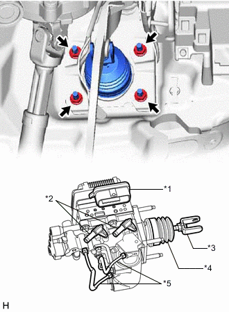
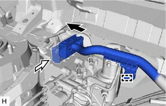
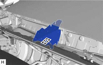
*1 Connector Portion *2 Union *3 Push Rod Clevis *4 Boot *5 Front No. 2 Brake Tube Install the brake booster with master cylinder assembly with the 4 nuts.
- Torque:
- 12.7 N*m { 130 kgf*cm, 9 ft.*lbf }
Note
-
Do not kink or damage the brake lines.
-
Do not carry the brake booster with master cylinder assembly by the portion shown in the illustration.
-
Be careful not to allow brake fluid to enter the connector of ECU.
-
If installing a new brake booster with master cylinder assembly, do not remove the hole plugs before connecting the brake lines because the brake booster with master cylinder is filled with brake fluid.
-
Engage the grommet of the brake line.
-
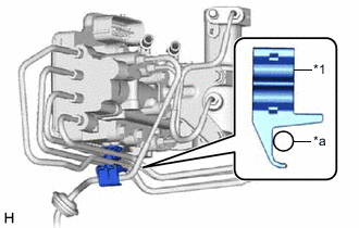
*1 No. 1 Brake Tube Clamp *a Brake Line Set the brake line to the No. 1 brake tube clamp as shown in the illustration.
Note
Securely install the brake line so that it contacts the No. 1 brake tube clamp as shown in the illustration.
-
Using a union nut wrench, connect the brake line to the front flexible hose RH.
- Torque:
- 15.2 N*m { 155 kgf*cm, 11 ft.*lbf }
Note
-
Do not kink or damage the brake lines.
-
Use the formula to calculate special torque values for situations where the union nut wrench is combined with a torque wrench.
-
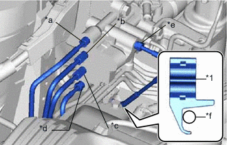
*1 No. 1 Brake Tube Clamp *a To Front Wheel Cylinder LH *b To Rear Wheel Cylinder RH *c To Brake Booster Pump Assembly *d To Rear Wheel Cylinder LH *e To Front Wheel Cylinder RH *f Brake Line Using the union nut wrench, connect each brake line to the brake booster with master cylinder assembly as shown in the illustration.
- Torque:
- 15.2 N*m { 155 kgf*cm, 11 ft.*lbf }
Note
-
Do not kink or damage the brake lines.
-
Securely install the brake line so that it contacts the No. 1 brake tube clamp as shown in the illustration.
-
Use the formula to calculate special torque values for situations where the union nut wrench is combined with a torque wrench.
-
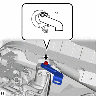
*a Stopper Install the wire harness clamp bracket to the brake booster with master cylinder assembly with the bolt.
- Torque:
- 8.0 N*m { 82 kgf*cm, 71 in.*lbf }
Note
Securely install the wire harness clamp bracket so that its stopper contacts the brake booster with master cylinder assembly as shown in the illustration.
-

Connect the connector 
Lock the lock lever Connect the connector to the brake booster with master cylinder assembly.
Note
-
Make sure that the connector can be connected smoothly. Do not allow water, oil or dirt to enter.
-
Make sure that the connector lock is locked securely.
-
-
Engage the clamp.
-
-
CONNECT NO. 2 BRAKE ACTUATOR HOSE
-
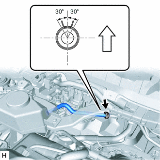
Up Connect the No. 2 brake actuator hose to the No. 1 brake actuator tube, and slide the clip to secure it.
Note
-
Make sure to match the identification mark (yellow) on the No. 2 brake actuator hose with the No. 1 brake actuator tube.
-
Make sure to install the hose to the proper location.
-
Install the clip within the range shown in the illustration.
-
-
-
CONNECT NO. 1 RESERVOIR HOSE
-
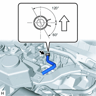
Up Connect the No. 1 reservoir hose to the brake booster with master cylinder assembly, and slide the clip to secure it.
Note
-
Make sure to match the identification mark (white (unpainted color)) on the No. 1 reservoir hose and brake booster with master cylinder assembly.
-
When connecting the No. 1 reservoir hose, face the identification mark up.
-
Make sure to install the hose to the proper location.
-
Install the clip within the range shown in the illustration.
-
-
-
CONNECT NO. 2 RESERVOIR HOSE
-
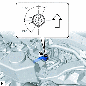
Up Connect the No. 2 reservoir hose to the brake booster with master cylinder assembly, and slide the clip to secure it.
Note
-
Make sure to match the identification mark (green) on the No. 2 reservoir hose and brake booster with master cylinder assembly.
-
When connecting the No. 2 reservoir hose, face the identification mark up.
-
Make sure to install the hose to the proper location.
-
Install the clip within the range shown in the illustration.
-
-
-
BLEED NO. 1 BRAKE ACTUATOR TUBE
-
Add brake fluid into the reservoir.
-
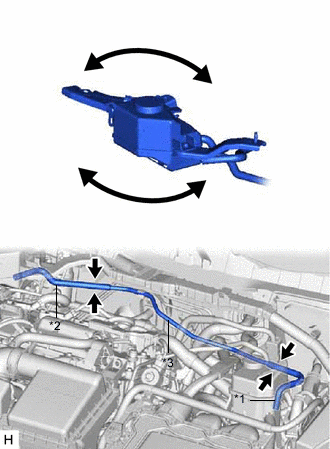
*1 Brake Actuator Hose *2 No. 2 Brake Actuator Hose *3 No. 1 Brake Actuator Tube Lift up the brake master cylinder reservoir assembly as far as possible and rock it back and forth to bleed air from the No. 1 brake actuator tube.
Note
-
Do not damage the hoses.
-
Do not spill brake fluid.
-
Continue this procedure until only a minor amount of air remains in the brake actuator tube.
-
-
-
INSTALL BRAKE MASTER CYLINDER RESERVOIR WITH BRACKET
-
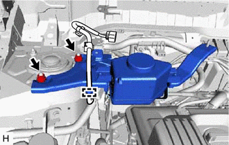
Install the brake master cylinder reservoir with bracket with the 2 nuts.
- Torque:
- 50 N*m { 510 kgf*cm, 37 ft.*lbf }
-
Engage the clamp to install the wire harness.
-
-
INSTALL PUSH ROD PIN
-
INSTALL BRAKE PEDAL RETURN SPRING
-
CONNECT NO. 2 STEERING INTERMEDIATE SHAFT ASSEMBLY
-
Connect the No. 2 steering intermediate shaft assembly to the steering column assembly.
-
-
FILL RESERVOIR WITH BRAKE FLUID
-
CONNECT CABLE TO AUXILIARY BATTERY NEGATIVE TERMINAL
for Wagon: Click here
for Hatchback: Click here
-
BLEED BRAKE SYSTEM
-
INSPECT AND ADJUST BRAKE PEDAL
-
OBTAIN ZERO POINT OF YAW RATE AND ACCELERATION SENSOR
Tech Tips
After the brake booster with master cylinder assembly is replaced, obtain the zero point of the yaw rate and acceleration sensor.
-
INSTALL NO. 1 INSTRUMENT PANEL UNDER COVER SUB-ASSEMBLY
-
INSTALL OUTER COWL TOP PANEL
-
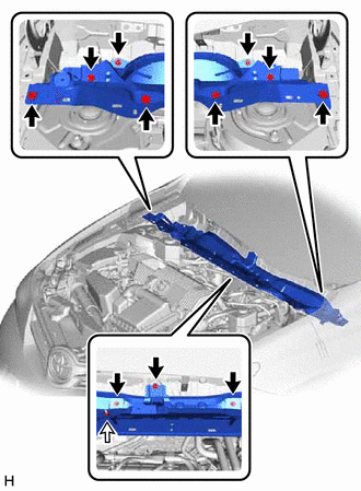
Bolt Nut Install the outer cowl top panel with the 11 bolts and nut.
- Torque:
- 12 N*m { 122 kgf*cm, 9 ft.*lbf }
-
-
INSTALL NO. 2 HEATER AIR DUCT SPLASH SHIELD SEAL
-
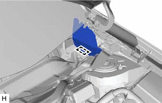
Engage the clamp to install the No. 2 heater air duct splash shield seal to the outer cowl top panel.
-
-
INSTALL WATER GUARD PLATE LH
-
Engage the clamp to install the water guard plate LH to the outer cowl top panel.
-
-
INSTALL WINDSHIELD WIPER MOTOR AND LINK ASSEMBLY