BRAKE BOOSTER PUMP(for RHD) INSTALLATION

PROCEDURE
-
INSTALL BRAKE BOOSTER PUMP ASSEMBLY
-
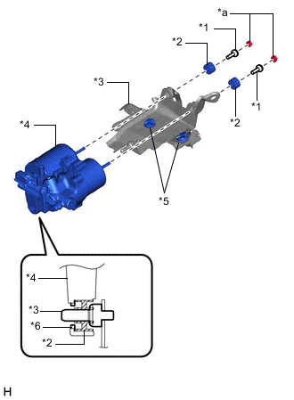
*1 Brake Actuator Case Collar *2 Brake Booster Pump Bushing *3 Brake Actuator Bracket Assembly *4 Brake Booster Pump Assembly *5 Brake Actuator Bracket Cushion *6 Brake Booster Pump Collar *a Nut Install the brake booster pump assembly, 2 brake booster pump bushings and 2 brake actuator case collars to the brake actuator bracket assembly with the 2 nuts.
- Torque:
- 5.4 N*m { 55 kgf*cm, 48 in.*lbf }
Note
-
Do not drop the brake booster pump assembly when carrying it.
-
Do not carry the brake booster pump assembly by the connector.
-
When installing the brake booster pump assembly to the brake actuator bracket assembly, confirm that the 2 brake actuator bracket cushions are on the brake actuator bracket assembly, and brake booster pump bushing and brake booster pump collar are on the brake booster pump assembly.
-
Do not remove the hole plug before installing a new brake booster pump assembly because the brake booster pump assembly is filled with brake fluid.
-
-
INSTALL BRAKE BOOSTER PUMP ASSEMBLY WITH BRACKET
-
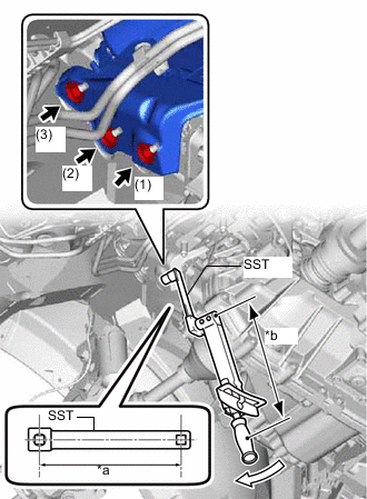
*a Length of SST 150 mm (5.91 in.) *b Length of Torque Wrench 250 mm (9.84 in.) 
Turn Using SST, install the brake booster pump assembly with bracket with the 3 nuts.
- SST
- 09961-00950
- Torque:
- without SST [Torque wrench (N*m (kgf*cm, ft.*lbf))]
- 19 N*m { 194 kgf*cm, 14 ft.*lbf }
- with SST [Reading of Torque wrench (N*m (kgf*cm, ft.*lbf))]
- 11.9 N*m { 121 kgf*cm, 9 ft.*lbf }
Note
-
This torque value is effective when SST is parallel to the torque wrench.
-
The "with SST" torque value is effective when using SST with a fulcrum length of 150 mm (5.91 in.).
-
The "with SST" torque value is effective when using a torque wrench with a fulcrum length of 250 mm (9.84 in.).
-
If using a torque wrench with a different length, or connecting the torque wrench and SST at an angle, refer to the alternate values.
-
Tighten the 3 nuts in the order shown in the illustration.
-
Do not damage the fuel lines, brake lines and wire harness.
-
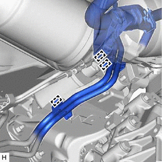
Engage the wire harness clamp and 2 fuel line clamps to the brake actuator bracket assembly.
Note
Do not kink or damage the fuel lines.
-
Engage the clamp to install the front No. 4 brake tube to the brake actuator bracket assembly.
Note
Do not kink or damage the front No. 4 brake tube.
-
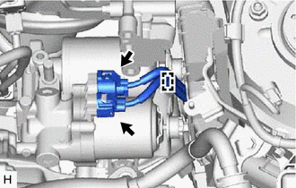
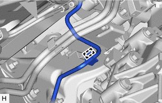
Engage the clamp to install the wire harness to the brake booster pump bracket assembly.
-
Connect the 2 connectors to the brake booster pump assembly.
-
-
INSTALL FRONT NO. 1 BRAKE TUBE
-
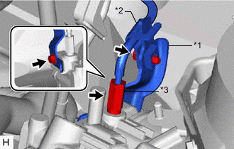
*1 No. 1 Brake Tube Clamp Bracket *2 No. 6 Brake Tube Clamp *3 Front No. 1 Brake Tube Install the No. 1 brake tube clamp bracket to the brake booster pump assembly with the bolt.
- Torque:
- 7.0 N*m { 71 kgf*cm, 62 in.*lbf }
-
Using a union nut wrench, connect the front No. 1 brake tube to the brake booster pump assembly to install it.
- Torque:
- 15.2 N*m { 155 kgf*cm, 11 ft.*lbf }
Note
Use the formula to calculate special torque values for situations where the union nut wrench is combined with a torque wrench.
-
Install the No. 6 brake tube clamp to the No. 1 brake tube clamp bracket with the bolt.
- Torque:
- 7.0 N*m { 71 kgf*cm, 62 in.*lbf }
-
-
CONNECT BRAKE ACTUATOR HOSE
-
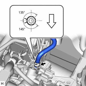
Front of vehicle Connect the brake actuator hose to the brake booster pump assembly.
Note
-
Make sure to match the identification mark (yellowish green) on the hose with the brake booster pump rib.
-
Make sure to install the hose to the proper location.
-
Install the clip within the range shown in the illustration.
-
-
-
INSTALL NO. 5 BRAKE ACTUATOR BRACKET
-
INSTALL FRONT SUSPENSION CROSSMEMBER SUB-ASSEMBLY
-
SEPARATE BRAKE MASTER CYLINDER RESERVOIR WITH BRACKET
-
BLEED NO. 1 BRAKE ACTUATOR TUBE
-
INSTALL BRAKE MASTER CYLINDER RESERVOIR WITH BRACKET
-
FILL RESERVOIR WITH BRAKE FLUID
-
CONNECT CABLE TO AUXILIARY BATTERY NEGATIVE TERMINAL
-
BLEED BRAKE SYSTEM
-
INSTALL OUTER COWL TOP PANEL
-
INSTALL NO. 2 HEATER AIR DUCT SPLASH SHIELD SEAL
-
INSTALL WATER GUARD PLATE LH
-
INSTALL WINDSHIELD WIPER MOTOR AND LINK ASSEMBLY