ELECTRONICALLY CONTROLLED BRAKE SYSTEM, Diagnostic DTC:C1247/47, C1346/71, C1392/48

| DTC Code | DTC Name |
|---|---|
| C1247/47 | Stroke Sensor Malfunction |
| C1346/71 | Stroke Sensor Zero Point Learning Malfunction (Test Mode DTC) |
| C1392/48 | Stroke Sensor Zero Point Calibration Undone |
DESCRIPTION
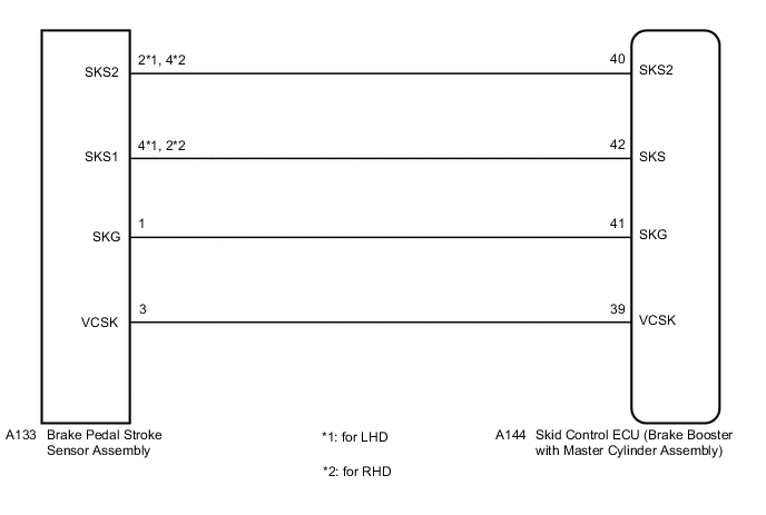
The brake pedal stroke sensor assembly sends a signal about the pedal stroke to the skid control ECU (brake booster with master cylinder assembly).
DTC C1346/71 will be cleared when the brake pedal stroke sensor assembly sends a brake pedal stroke sensor assembly signal or when Test Mode ends. DTC C1346/71 is output only in Test Mode.
| DTC No. | Detection Item | INF Code | DTC Detection Condition | Trouble Area | Note |
|---|---|---|---|---|---|
| C1247/47 | Stroke Sensor Malfunction | 211 212 213 214 215 218 219 223 |
|
|
Electronically controlled brake system DTC |
| C1346/71 | Stroke Sensor Zero Point Learning Malfunction (Test Mode DTC) | - | Detected only during Test Mode. |
|
Electronically controlled brake system Test Mode DTC |
| C1392/48 | Stroke Sensor Zero Point Calibration Undone | - | Zero point calibration of brake pedal stroke sensor assembly is unfinished. |
|
Electronically controlled brake system DTC |
WIRING DIAGRAM
CAUTION / NOTICE / HINT
Note
When replacing the skid control ECU (brake booster with master cylinder assembly) or brake pedal stroke sensor assembly, perform initialization and calibration of the linear solenoid valve.
PROCEDURE
-
CHECK BRAKE PEDAL
-
Check that the brake pedal and the brake pedal stroke sensor assembly are properly installed and that the pedal can be depressed normally.
-
Check and adjust the brake pedal height.
for LHD: Click here
for RHD: Click here
-
Adjust the brake pedal stroke sensor assembly.
for LHD: Click here
for RHD: Click here
Result Proceed to NEXT
NEXT 
-
-
CHECK HARNESS AND CONNECTOR (BRAKE BOOSTER WITH MASTER CYLINDER ASSEMBLY - BRAKE PEDAL STROKE SENSOR ASSEMBLY)
-
Make sure that there is no looseness at the locking part and the connecting part of the connectors.
-
Disconnect the A144 skid control ECU (brake booster with master cylinder assembly) connector.
-
Disconnect the A133 brake pedal stroke sensor assembly connector.
-
Check both the connector case and the terminal for deformation and corrosion.
OK No deformation or corrosion. -
Measure the resistance according to the value(s) in the table below.
Standard Resistance for LHD Tester Connection Condition Specified Condition A144-39 (VCSK) - A133-3 (VCSK) Always Below 1 Ω A144-39 (VCSK) - Body ground Always 10 kΩ or higher A133-3 (VCSK) - Body ground Always 10 kΩ or higher A144-41 (SKG) - A133-1 (SKG) Always Below 1 Ω A144-41 (SKG) - Body ground Always 10 kΩ or higher A133-1 (SKG) - Body ground Always 10 kΩ or higher A144-42 (SKS) - A133-4 (SKS1) Always Below 1 Ω A144-42 (SKS) - Body ground Always 10 kΩ or higher A133-4 (SKS1) - Body ground Always 10 kΩ or higher A144-40 (SKS2) - A133-2 (SKS2) Always Below 1 Ω A144-40 (SKS2) - Body ground Always 10 kΩ or higher A133-2 (SKS2) - Body ground Always 10 kΩ or higher for RHD Tester Connection Condition Specified Condition A144-39 (VCSK) - A133-3 (VCSK) Always Below 1 Ω A144-39 (VCSK) - Body ground Always 10 kΩ or higher A133-3 (VCSK) - Body ground Always 10 kΩ or higher A144-41 (SKG) - A133-1 (SKG) Always Below 1 Ω A144-41 (SKG) - Body ground Always 10 kΩ or higher A133-1 (SKG) - Body ground Always 10 kΩ or higher A144-42 (SKS) - A133-2 (SKS1) Always Below 1 Ω A144-42 (SKS) - Body ground Always 10 kΩ or higher A133-2 (SKS1) - Body ground Always 10 kΩ or higher A144-40 (SKS2) - A133-4 (SKS2) Always Below 1 Ω A144-40 (SKS2) - Body ground Always 10 kΩ or higher A133-4 (SKS2) - Body ground Always 10 kΩ or higher Result Proceed to OK NG
NG 
REPAIR OR REPLACE HARNESS OR CONNECTOR
OK
-
-
INSPECT BRAKE BOOSTER WITH MASTER CYLINDER ASSEMBLY (SENSOR OUTPUT)
-
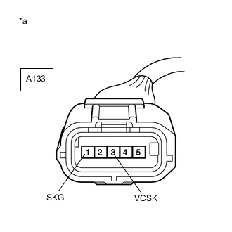
*a Front view of wire harness connector
(to Brake Pedal Stroke Sensor Assembly)
Reconnect the A144 skid control ECU (brake booster with master cylinder assembly) connector.
-
Turn the power switch on (IG).
-
Measure the voltage according to the value(s) in the table below.
Standard Voltage Tester Connection Condition Specified Condition A133-3 (VCSK) - A133-1 (SKG) Power switch on (IG) 4.84 to 5.16 V Result Proceed to OK NG
OK
REPLACE BRAKE PEDAL STROKE SENSOR ASSEMBLY for LHD: Click here
REPLACE BRAKE PEDAL STROKE SENSOR ASSEMBLY for RHD: Click hereNG
REPLACE BRAKE BOOSTER WITH MASTER CYLINDER ASSEMBLY for LHD: Click here
REPLACE BRAKE BOOSTER WITH MASTER CYLINDER ASSEMBLY for RHD: Click here -