AFS (ADAPTIVE FRONT-LIGHTING SYSTEM) AFS ECU Power Source Circuit
DESCRIPTION
This circuit detects the state of the power switch, and sends it to the AFS ECU (headlight swivel ECU assembly).
WIRING DIAGRAM
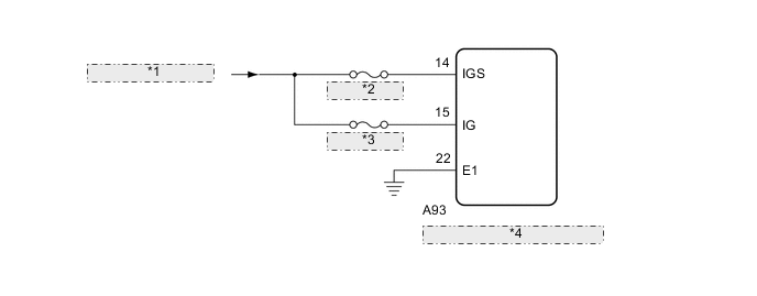
| *1 | from IG1 NO. 1 Relay |
| *2 | ECU-IG NO. 1 |
| *3 | ECU-IG NO. 3 |
| *4 | AFS ECU (Headlight Swivel ECU Assembly) |
CAUTION / NOTICE / HINT
Note
-
Inspect the fuses for circuits related to this system before performing the following procedure.
-
If the AFS ECU (headlight swivel ECU assembly) has been replaced, it is necessary to synchronize the vehicle information and initialize the AFS ECU (headlight swivel ECU assembly).
PROCEDURE
-
READ VALUE USING GTS
-
Connect the GTS to the DLC3.
-
Turn the power switch on (IG).
-
Turn the GTS on.
-
Enter the following menus: Body Electrical / AFS / Data List.
-
Read the display on the GTS.
Body Electrical > AFS > Data ListTester Display Measurement Item Range Normal Condition Diagnostic Note +B IG power supply voltage value 0.00 to 19.75 V 11.00 to 14.00 V -
Body Electrical > AFS > Data ListTester Display +B OK Normal condition listed above is displayed. Result Proceed to OK NG
OK 
PROCEED TO NEXT SUSPECTED AREA SHOWN IN PROBLEM SYMPTOMS TABLE Click here
NG 
-
-
CHECK HARNESS AND CONNECTOR (AFS ECU (HEADLIGHT SWIVEL ECU ASSEMBLY) - POWER SOURCE AND BODY GROUND)
-
Disconnect the A93 AFS ECU (headlight swivel ECU assembly) connector.
-
Measure the voltage according to the value(s) in the table below.
Standard Voltage Tester Connection Condition Specified Condition A93-14 (IGS) - Body ground Power switch on (IG) 11 to 14 V Power switch off Below 1 V A93-15 (IG) - Body ground Power switch on (IG) 11 to 14 V Power switch off Below 1 V -
Measure the resistance according to the value(s) in the table below.
Standard Resistance Tester Connection Condition Specified Condition A93-22 (E1) - Body ground Always Below 1 Ω Result Proceed to OK NG
OK
REPLACE AFS ECU (HEADLIGHT SWIVEL ECU ASSEMBLY) Click here
NG
REPAIR OR REPLACE HARNESS OR CONNECTOR
-