RADIATOR INSTALLATION
PROCEDURE
-
INSTALL RADIATOR DRAIN COCK PLUG
-
Install the O-ring to the radiator drain cock plug.
Note
Replace the O-ring if it is damaged.
-
Install the radiator drain cock plug.
-
-
INSTALL RADIATOR ASSEMBLY
-
Install the fan shroud to the radiator assembly with the 2 bolts.
- Torque:
- 7.0 N*m { 71 kgf*cm, 62 in.*lbf }
-
Install the No. 1 radiator hose and slide the clip to secure it.
-
Install the 2 lower radiator supports.
-
Install the radiator assembly with the fan shroud.
Note
Do not apply excessive force to the condenser assembly or pipe when installing the radiator assembly.
-
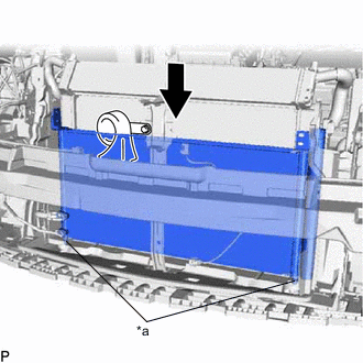
*a Guide Engage the 2 guides to connect the condenser assembly as shown in the illustration.
Note
Do not damage the condenser assembly or radiator assembly when connecting the condenser assembly.
-
Connect the 2 clamps and wire harness.
-
Connect the cooling fan motor connector and No. 2 cooling fan motor connector.
-
-
INSTALL NO. 2 FAN SHROUD
-
Engage the 2 claws and 2 guides and install the No. 2 fan shroud to the radiator assembly.
-
Install the 2 bolts.
- Torque:
- 7.0 N*m { 71 kgf*cm, 62 in.*lbf }
-
Install the 2 radiator support cushions to the No. 2 fan shroud.
-
-
CONNECT NO. 5 INVERTER COOLING HOSE
-
Connect the 3 clamps and No. 5 inverter cooling hose to the fan shroud.
-
-
CONNECT NO. 3 WATER BY-PASS HOSE
-
Connect the No. 3 water by-pass hose and slide the clip to secure it.
-
Connect the 4 clamps.
-
-
CONNECT WATER BY-PASS HOSE
-
Connect the water by-pass hose and slide the clip to secure it.
-
-
INSTALL UPPER RADIATOR SUPPORT SUB-ASSEMBLY
-
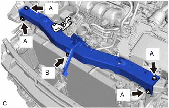
Install the upper radiator support sub-assembly with the 5 bolts.
- Torque:
- Bolt A
- 12.5 N*m { 127 kgf*cm, 9 ft.*lbf }
- Bolt B
- 8.0 N*m { 82 kgf*cm, 71 in.*lbf }
-
Connect the wire harness with the 2 clamps. (w/ Engine Hood Courtesy Switch)
-
Connect the engine hood courtesy switch connector. (w/ Engine Hood Courtesy Switch)
-
Connect the hood lock control cable assembly to the upper radiator support sub-assembly with the 2 clamps.
-
Connect the hood lock control cable assembly to the hood lock control lever sub-assembly.
-
-
INSTALL RADIATOR SUPPORT RH
-
Install the radiator support cushion to the radiator support RH.
-
Install the radiator support RH with the bolt.
- Torque:
- 19 N*m { 194 kgf*cm, 14 ft.*lbf }
-
Connect the clamp and No. 2 water by-pass hose to the hood support rod bracket.
-
-
INSTALL RADIATOR SUPPORT LH
-
Install the radiator support cushion to the radiator support LH.
-
Install the radiator support LH with the bolt.
- Torque:
- 19 N*m { 194 kgf*cm, 14 ft.*lbf }
-
-
CONNECT NO. 2 RADIATOR HOSE
-
Connect the No. 2 radiator hose and slide the clip to secure it.
-
-
CONNECT NO. 1 RADIATOR HOSE
-
Connect the No. 1 radiator hose and slide the clip to secure it.
-
-
INSTALL NO. 1 INVERTER BRACKET
-
INSTALL AIR CLEANER CASE SUB-ASSEMBLY
-
INSTALL INLET AIR CLEANER ASSEMBLY
-
INSTALL AIR CLEANER CAP SUB-ASSEMBLY
-
INSTALL THERMISTOR ASSEMBLY
-
INSTALL HEADLIGHT ASSEMBLY LH
-
INSTALL HEADLIGHT ASSEMBLY RH
Tech Tips
Use the same procedure as for the LH side.
-
ADD ENGINE COOLANT (for Engine)
-
INSPECT FOR COOLANT LEAK (for Engine)
-
INSTALL NO. 1 ENGINE UNDER COVER