EGR COOLER INSTALLATION
PROCEDURE
-
INSTALL EGR COOLER SUB-ASSEMBLY
-
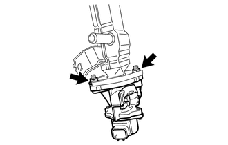
Temporarily install a new EGR valve gasket and the EGR cooler sub-assembly with the 2 nuts.
-
Install a new EGR cooler gasket and set the EGR valve with cooler assembly in place.
-
Using an E8 "TORX" socket wrench, install the 4 stud bolts.
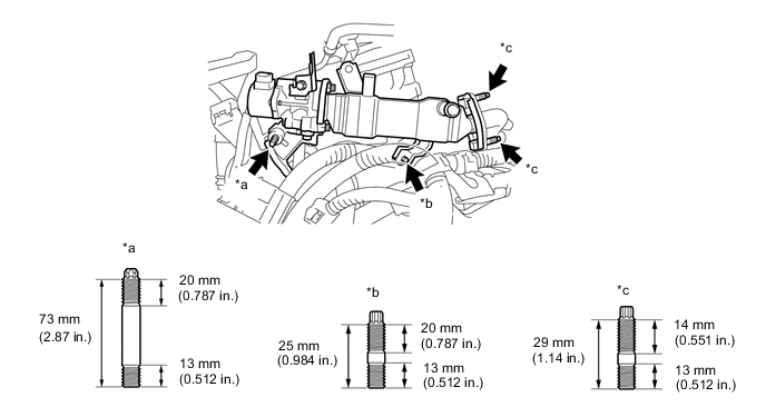
*a Stud Bolt A *b Stud Bolt B *c Stud Bolt C - - - Torque:
- Stud Bolt A and Stud Bolt B
- 9.5 N*m { 97 kgf*cm, 84 in.*lbf }
- Stud Bolt C
- 5.0 N*m { 51 kgf*cm, 44 in.*lbf }
-
Temporarily install the 2 nuts (B), 2 nuts (C) and bolt.
Tech Tips
The type B nut and type C nut are non-reusable.
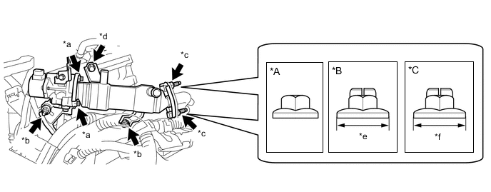
*A Type A *B Type B *C Type C - - *a Nut A *b Nut B *c Nut C *d Bolt *e 18 mm (0.709 in.) *f 17 mm (0.669 in.) -
Tighten the 2 nuts (A).
- Torque:
- 21 N*m { 214 kgf*cm, 15 ft.*lbf }
-
Tighten the 2 nuts (B) and bolt.
- Torque:
- 21 N*m { 214 kgf*cm, 15 ft.*lbf }
Note
Make sure that all installation surfaces of the EGR valve with cooler assembly are in even contact when tightening the bolt and nuts.
-
Tighten the 2 nuts (C).
- Torque:
- Type A
- 21 N*m { 214 kgf*cm, 15 ft.*lbf }
- Type B
- 37 N*m { 377 kgf*cm, 27 ft.*lbf }
- Type C
- 26 N*m { 265 kgf*cm, 19 ft.*lbf }
-
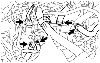
Connect the connector and engage the wire harness clamp.
-
Connect the 4 water hoses and slide the 4 clips to secure them.
-
-
INSTALL EGR PIPE ASSEMBLY
-
INSTALL AIR CLEANER CASE SUB-ASSEMBLY
-
INSTALL INLET AIR CLEANER ASSEMBLY
-
INSTALL AIR CLEANER CAP SUB-ASSEMBLY
-
INSTALL NO. 2 CYLINDER HEAD COVER
-
ADD ENGINE COOLANT (for Engine)
-
INSPECT FOR COOLANT LEAK (for Engine)
-
INSTALL OUTER COWL TOP PANEL (for LHD)
-
INSTALL OUTER COWL TOP PANEL (for RHD)
-
INSTALL NO. 2 HEATER AIR DUCT SPLASH SHIELD SEAL (for LHD)
-
INSTALL NO. 2 HEATER AIR DUCT SPLASH SHIELD SEAL (for RHD)
-
INSTALL WATER GUARD PLATE LH (for LHD)
-
INSTALL WATER GUARD PLATE LH (for RHD)
-
INSTALL WINDSHIELD WIPER MOTOR AND LINK ASSEMBLY