CYLINDER BLOCK DISASSEMBLY

PROCEDURE
-
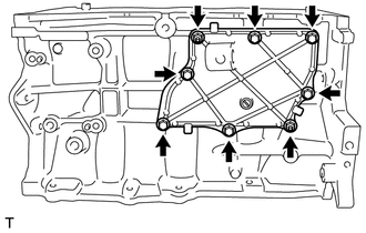
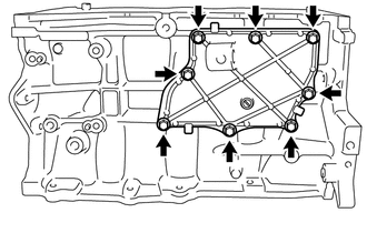
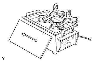
REMOVE NO. 1 VENTLATION CASE
Tech Tips
There are 2 installation types for the No. 1 ventilation case.
Depending on the installation type, the number of bolts, nuts and stud bolts used will vary.
-
Type A:
-
Remove the 6 bolts and 2 nuts.
-
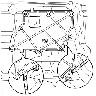
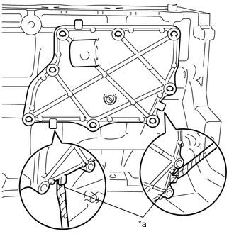
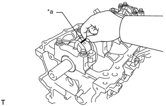
*a Protective Tape Remove the No. 1 ventilation case by prying between the No. 1 ventilation case and cylinder block sub-assembly with a screwdriver as shown in the illustration.
Note
Be careful not to damage the contact surfaces of the cylinder block and No. 1 ventilation case.
Tech Tips
Tape the screwdriver tip before use.
-
Using an E6 "TORX" socket, remove the 2 stud bolts.
-
-
Type B:
-
Remove the 8 bolts.
-
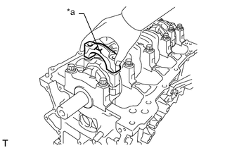
*a Protective Tape Remove the No. 1 ventilation case by prying between the ventilation case and cylinder block sub-assembly with a screwdriver as shown in the illustration.
Note
Be careful not to damage the contact surfaces of the cylinder block and No. 1 ventilation case.
Tech Tips
Tape the screwdriver tip before use.
-
-
-
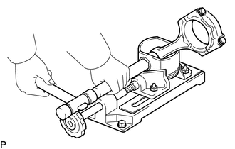
INSPECT CONNECTING ROD THRUST CLEARANCE
-
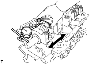
Using a dial indicator, measure the thrust clearance while moving the connecting rod cap back and forth.
Standard Thrust Clearance 0.160 to 0.342 mm (0.00630 to 0.0135 in.) Maximum Thrust Clearance 0.342 mm (0.0135 in.) If the thrust clearance is greater than the maximum, replace the connecting rod as necessary. If necessary, replace the crankshaft.
-
-
INSPECT CONNECTING ROD OIL CLEARANCE
-
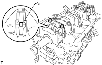
*a Matchmark Check that the matchmarks on the connecting rod and connecting rod cap are aligned to ensure correct reassembly.
Tech Tips
The matchmarks on the connecting rods and connecting rod caps are provided to ensure correct reassembly.
-
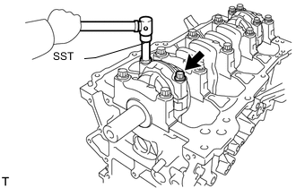
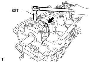
Using SST, uniformly loosen the 2 connecting rod bolts.
- SST
- 09205-16011
-
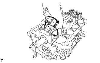
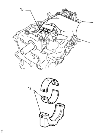
Using the 2 removed connecting rod bolts, remove the connecting rod cap and lower crankshaft bearing by wiggling the connecting rod cap right and left.
Tech Tips
Keep the lower crankshaft bearing inserted in the connecting rod cap.
-
Clean the crank pin and bearing.
-
Check the crank pin and bearing for pitting and scratches.
If the crank pin or bearing is damaged, replace the bearings. If necessary, replace the crankshaft.
-
*a Plastigage Lay a strip of plastigage on the crank pin.
-
*a Front Mark Check that the front mark of the connecting rod cap is facing forward and install the connecting rod cap.
-
Apply a light coat of engine oil to the threads and under the heads of the connecting rod bolts.
-
Install the connecting rod cap bolts.
Note
The connecting rod bolts should be tightened in 2 progressive steps.
-
Step 1:
-
Using SST, install and alternately tighten the connecting rod bolts in several steps.
- SST
- 09205-16011
- Torque:
- 20 N*m { 204 kgf*cm, 15 ft.*lbf }
Note
Do not turn the crankshaft.
-
-
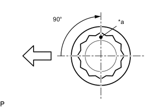
*a Paint Mark 
Engine Front Step 2:
-
Mark the front of the connecting rod bolts with paint.
-
Tighten the connecting rod bolts 90° as shown in the illustration.
Note
Do not turn the crankshaft.
-
-
Remove the 2 connecting rod bolts and connecting rod cap.
Tech Tips
Keep the lower crankshaft bearing inserted in the connecting rod cap.
-
*a Mark 1, 2 or 3 *b Plastigage Measure the Plastigage at its widest point.
Standard Oil Clearance 0.014 to 0.038 mm (0.000551 to 0.00150 in.) Maximum Oil Clearance 0.070 mm (0.00276 in.) If the oil clearance is more than the maximum, replace the connecting rod bearings. If necessary, inspect the crankshaft.
Note
Remove the Plastigage completely after the measurement.
Tech Tips
If replacing a connecting rod bearing, replace it with one that has the same number as its respective connecting rod cap. Each bearing standard thickness is indicated by a 1, 2, or 3 mark on its surface.
Standard Connecting Rod Large End Bore Diameter Mark Specified Condition 1 47.000 to 47.008 mm (1.85039 to 1.85071 in.) 2 47.009 to 47.016 mm (1.85074 to 1.85102 in.) 3 47.017 to 47.024 mm (1.85106 to 1.85133 in.) Standard Connecting Rod Bearing Thickness Mark Specified Condition 1 1.489 to 1.493 mm (0.05862 to 0.05878 in.) 2 1.494 to 1.497 mm (0.05882 to 0.05894 in.) 3 1.498 to 1.501 mm (0.05898 to 0.05909 in.) Standard Crankshaft Pin Diameter 43.992 to 44.000 mm (1.7320 to 1.7323 in.) -
Perform the inspection above for each cylinder.
-
-
REMOVE PISTON SUB-ASSEMBLY WITH CONNECTING ROD
-
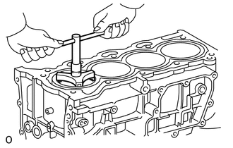
Using a ridge reamer, scrape off any carbon on the top of the cylinder.
-
Push the piston, connecting rod and upper crankshaft bearing through the top of the cylinder block sub-assembly.
Tech Tips
-
Keep the bearing, connecting rod and cap together.
-
Arrange the pistons and connecting rods in the correct order.
-
Be sure to arrange the removed pistons and connecting rods in such a way that they can be reinstalled exactly as before.
-
-
-
REMOVE CONNECTING ROD BEARING
-
Remove the connecting rod bearings.
Tech Tips
Arrange the removed parts in the correct order.
-
-
REMOVE PISTON RING SET
-
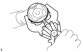
Using a piston ring expander, remove the No. 1 compression ring and No. 2 compression ring.
-
for 2-piece Type:
-
Remove the oil ring and oil ring expander by hand.
Tech Tips
Arrange the removed parts in the correct order.
-
-
for 3-piece Type:
-
Remove the oil ring expander, upper side rail and lower side rail by hand.
Tech Tips
Arrange the removed parts in the correct order.
-
-
-
REMOVE PISTON
-
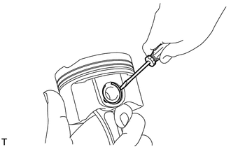
Using a screwdriver, pry out the 2 piston pin hole snap rings.
-
Gradually heat each piston to approximately 80 to 90°C (176 to 194°F).
-
Using a plastic hammer and brass bar, lightly tap out the piston pin and remove the connecting rod.
Tech Tips
-
The piston and piston pin are a matched set.
-
Arrange the pistons, piston pins, piston rings, connecting rods and connecting rod bearings in the correct order.
-
-
-
INSPECT CRANKSHAFT THRUST CLEARANCE
-
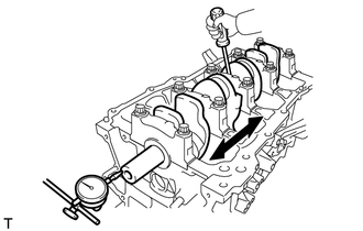
Using a dial indicator, measure the thrust clearance while prying the crankshaft back and forth with a screwdriver.
Standard Thrust Clearance 0.04 to 0.14 mm (0.00157 to 0.00551 in.) Maximum Thrust Clearance 0.18 mm (0.00709 in.) If the thrust clearance is more than the maximum, replace the thrust washers as a set. If necessary, replace the crankshaft.
Tech Tips
The thrust washer thickness is 2.43 to 2.48 mm (0.0957 to 0.0976 in.).
-
-
REMOVE CRANKSHAFT
-
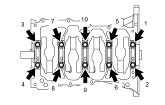
Uniformly loosen and remove the 10 crankshaft bearing cap set bolts in the order shown in the illustration.
-
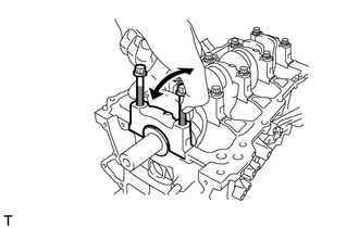
Using the 2 removed crankshaft bearing cap set bolts, remove the 5 crankshaft bearing caps and 5 lower crankshaft bearings.
Note
Insert the bolts into the caps in turn. Ease the cap out by gently pulling it up while applying force toward the front and back of the cylinder block sub-assembly as shown in the illustration. Take care not to damage the contact surfaces of the cap and cylinder block sub-assembly.
Tech Tips
-
Keep the lower crankshaft bearing and crankshaft bearing cap together as a set.
-
Arrange the crankshaft bearing caps in the correct order.
-
-
Lift out the crankshaft.
-
Check each crankshaft journal and bearing for pitting and scratches.
If the journal or bearing is damaged, replace the bearings. If necessary, replace the crankshaft.
-
-
REMOVE UPPER CRANKSHAFT THRUST WASHER
-
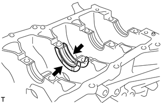
Remove the 2 upper crankshaft thrust washers from the cylinder block sub-assembly.
-
-
REMOVE UPPER CRANKSHAFT BEARING
-
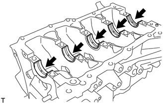
Remove the 5 upper crankshaft bearings from the cylinder block sub-assembly.
Tech Tips
Arrange the bearings in the correct order.
-
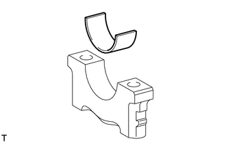
Remove the 5 lower crankshaft bearings from the 5 crankshaft bearing caps.
Tech Tips
Arrange the bearings in the correct order.
-
-
REMOVE NO. 1 OIL NOZZLE SUB-ASSEMBLY
-
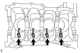
Using a 5 mm socket hexagon wrench, remove the 4 bolts and 4 No. 1 oil nozzle sub-assemblies.
-
-
CLEAN CYLINDER BLOCK SUB-ASSEMBLY
Note
If the cylinder block sub-assembly is washed at high temperatures, the cylinder liner will stick out beyond the cylinder block sub-assembly. Always wash the cylinder block sub-assembly at a temperature of 45°C (113°F) or less.
-
REMOVE STUD BOLT
Note
If a stud bolt is deformed or its threads are damaged, replace it.