ENGINE ASSEMBLY INSTALLATION
PROCEDURE
-
INSTALL ENGINE HANGER
-
REMOVE ENGINE FROM ENGINE STAND
-
Attach an engine sling device and hang the engine assembly.
Note
-
Adjust the angle of the sling device carefully to prevent the engine assembly or engine hangers from deforming or becoming damaged.
-
Servicing an engine assembly while it is hanging is dangerous. This can be done only when installing/removing the engine assembly to/from an engine stand.
-
-
Remove the engine assembly from the engine stand.
-
-
INSTALL FLYWHEEL SUB-ASSEMBLY
-
INSTALL TRANSMISSION INPUT DAMPER ASSEMBLY
-
INSTALL HYBRID VEHICLE TRANSAXLE ASSEMBLY
-
INSTALL ENGINE WIRE
-
Install the engine wire to the engine assembly with hybrid vehicle transaxle assembly.
-
-
INSTALL FLYWHEEL HOUSING SIDE COVER
-
INSTALL STARTER HOLE INSULATOR
-
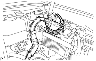
INSTALL RADIATOR PIPE
-
Install the No. 3 radiator hose to the cylinder head sub-assembly, and slide the clamp to secure it.
-
Install the radiator pipe to the hybrid vehicle transaxle assembly with the 2 bolts.
- Torque:
- 19 N*m { 194 kgf*cm, 14 ft.*lbf }
-
-
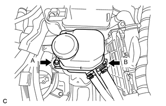
INSTALL ENGINE MOUNTING INSULATOR SUB-ASSEMBLY RH
Tech Tips
Perform this procedure only when replacement of the engine mounting insulator sub-assembly RH is necessary.
-
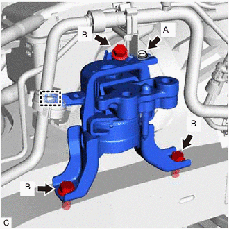
Install the engine mounting insulator sub-assembly RH with the 3 bolts (B).
- Torque:
- 95 N*m { 969 kgf*cm, 70 ft.*lbf }
-
Install the cooler pipe clamp bracket to the engine mounting insulator sub-assembly RH with the bolt (A).
- Torque:
- 9.8 N*m { 100 kgf*cm, 7 ft.*lbf }
-
Connect the cooler pipe clamp to the engine mounting insulator sub-assembly RH.
-
Install the radiator reservoir tank assembly with the 2 bolts.
- Torque:
- 5.0 N*m { 51 kgf*cm, 44 in.*lbf }
-
-
INSTALL ENGINE MOUNTING INSULATOR LH
Tech Tips
Perform this procedure only when replacement of the engine mounting insulator LH is necessary.
-
Install the engine mounting insulator LH with the 4 bolts.
- Torque:
- 95 N*m { 969 kgf*cm, 70 ft.*lbf }
-
-
TEMPORARILY INSTALL FRONT ENGINE MOUNTING INSULATOR
-
Temporarily install the front engine mounting insulator to the front engine mounting bracket with the through bolt and nut.
-
-
TEMPORARILY INSTALL REAR ENGINE MOUNTING INSULATOR
-
Temporarily install the rear engine mounting insulator to the rear engine mounting bracket with the through bolt.
-
-
INSTALL ENGINE ASSEMBLY WITH TRANSAXLE
-
Set the engine assembly with hybrid vehicle transaxle assembly on an engine lifter.
Note
-
Place height adjustment attachments and plate lift attachments under the engine assembly with hybrid vehicle transaxle.
-
Do not position height adjustment attachments or plate lift attachments under the front suspension crossmember sub-assembly.
Tech Tips
Place the engine assembly with hybrid vehicle transaxle assembly on wooden blocks or equivalent so that the engine is level.
-
-
Remove the 2 bolts, No. 1 engine hanger and No. 2 engine hanger.
-
Set the engine assembly with hybrid vehicle transaxle assembly and front suspension crossmember sub-assembly on an engine lifter.
-
Operate the engine lifter to lift the engine assembly with hybrid vehicle transaxle assembly and front suspension crossmember sub-assembly to the position where the engine mounting insulator sub-assembly RH and LH can be installed.
CAUTION:
Do not raise the engine assembly with hybrid vehicle transaxle assembly more than necessary. If the engine assembly with hybrid vehicle transaxle assembly is raised excessively, the vehicle may also be lifted up.
Note
-
Make sure that the engine assembly with hybrid vehicle transaxle assembly is clear of all wiring and hoses.
-
While raising the engine assembly with hybrid vehicle transaxle assembly into the vehicle, do not allow it to contact the vehicle.
-
-
Install the engine mounting insulator sub-assembly LH with the through bolt and nut.
- Torque:
- 56 N*m { 571 kgf*cm, 41 ft.*lbf }
Tech Tips
When tightening the through bolt, keep the nut from rotating.
-
Install the engine mounting insulator sub-assembly RH with the bolt and 2 nuts.
- Torque:
- Nut A
- 95 N*m { 969 kgf*cm, 70 ft.*lbf }
- Nut B
- 52 N*m { 530 kgf*cm, 38 ft.*lbf }
- Bolt
- 95 N*m { 969 kgf*cm, 70 ft.*lbf }
-
Install the front crossmember sub-assembly with the 4 bolts.
- Torque:
- 99 N*m { 1010 kgf*cm, 73 ft.*lbf }
-
Connect the front engine mounting insulator to the front crossmember sub-assembly with the 2 bolts.
- Torque:
- 95 N*m { 969 kgf*cm, 70 ft.*lbf }
-
-
INSTALL FRONT SUSPENSION CROSSMEMBER SUB-ASSEMBLY
-
INSTALL FRONT SUSPENSION MEMBER BRACE REAR LH
-
INSTALL FRONT SUSPENSION MEMBER BRACE REAR RH
Tech Tips
Perform the same procedure as for the LH side.
-
INSTALL FRONT SUSPENSION MEMBER REINFORCEMENT LH
-
INSTALL FRONT SUSPENSION MEMBER REINFORCEMENT RH
-
INSTALL ENGINE FRONT MOUNTING BRACKET LOWER REINFORCEMENT
-
FULLY TIGHTEN REAR ENGINE MOUNTING INSULATOR
-
Tighten the rear engine mounting insulator to the rear engine mounting bracket with the through bolt.
- Torque:
- 95 N*m { 969 kgf*cm, 70 ft.*lbf }
-
-
FULLY TIGHTEN FRONT ENGINE MOUNTING INSULATOR
-
Tighten the front engine mounting insulator to the front engine mounting bracket with the bolt and nut.
- Torque:
- 85 N*m { 867 kgf*cm, 63 ft.*lbf }
Tech Tips
Because the nut has its own stopper, do not turn the nut. Tighten the bolt with the nut secured.
-
-
INSTALL FRONT DRIVE SHAFT ASSEMBLY
-
INSTALL FRONT EXHAUST PIPE ASSEMBLY (TWC: Front and Rear Catalyst) (w/ Exhaust Heat Recirculation System)
-
INSTALL FRONT EXHAUST PIPE ASSEMBLY (TWC: Front and Rear Catalyst) (w/o Exhaust Heat Recirculation System)
-
INSTALL FRONT CENTER FLOOR BRACE SUB-ASSEMBLY
-
CONNECT NO. 1 STEERING COLUMN HOLE COVER SUB-ASSEMBLY
-
CONNECT NO. 2 STEERING INTERMEDIATE SHAFT ASSEMBLY
-
INSTALL COLUMN HOLE COVER SILENCER SHEET
-
INSTALL WIRE HARNESS
-
Connect the wire harness with the 2 clamps.
-
Connect the wire harness to the engine room junction block with the 3 clamps.
-
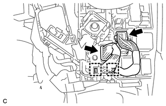
Connect the wire harness to the engine room junction block.
-
Connect the 2 connectors and 2 clamps to the engine room junction block.
-
Install the No. 1 engine room relay block cover.
-
Connect the ECM connector and push down the lever.
-
Connect the clamp.
-
-
INSTALL COMPRESSOR WITH MOTOR ASSEMBLY
-
CONNECT FUEL TUBE SUB-ASSEMBLY
-
CONNECT NO. 1 FUEL VAPOR FEED HOSE
-
Connect the No. 1 fuel vapor feed hose to the fuel pipe and slide the clip to secure it.
-
-
CONNECT HEATER HOSE
-
Connect the heater hose to the EGR cooler sub-assembly and slide the clip to secure it.
-
-
CONNECT INLET HEATER WATER HOSE A
-
Connect the inlet heater water hose A to the EGR cooler sub-assembly and slide the clip to secure it.
-
-
CONNECT OUTLET HEATER WATER HOSE A
-
Connect the outlet heater water hose A to the EGR cooler sub-assembly and slide the clip to secure it.
-
-
CONNECT NO. 5 INVERTER COOLING HOSE
-
Connect the No. 5 inverter cooling hose to the hybrid vehicle transaxle assembly and slide the clip to secure it.
-
-
CONNECT NO. 3 INVERTER COOLING HOSE
-
Connect the No. 3 inverter cooling hose to the hybrid vehicle transaxle assembly and slide the clip to secure it.
-
-
CONNECT NO. 4 WATER BY-PASS HOSE
-
Connect the No. 4 water by-pass hose to the radiator pipe assembly and slide the clip to secure it.
-
-
CONNECT NO. 2 RADIATOR HOSE
-
Connect the No. 2 radiator hose to the water inlet and slide the clip to secure it.
-
-
CONNECT NO. 1 RADIATOR HOSE
-
Connect the No. 1 radiator hose to the radiator pipe assembly and slide the clip to secure it.
-
-
INSTALL INVERTER TRAY BRACKET
-

Position the inverter tray bracket as shown in the illustration.
-
Temporarily install the bolt (B) to the inverter tray bracket.
-
Tighten the 5 bolts to the inverter tray bracket in the order of the bolt (A), bolt (C), bolt (D), bolt (E) and bolt (B).
- Torque:
- 18 N*m { 184 kgf*cm, 13 ft.*lbf }
-
Connect the 2 clamps to the inverter tray bracket.
-
-
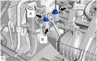
INSTALL INVERTER RESERVE TANK ASSEMBLY
-
Temporarily install the bolt (A) to the inverter reserve tank assembly.
-
Tighten the 2 bolts to the inverter reserve tank assembly in the order of the bolt (B) and bolt (A).
- Torque:
- 10 N*m { 102 kgf*cm, 7 ft.*lbf }
-
-
INSTALL INVERTER WITH CONVERTER ASSEMBLY
-
CONNECT NO. 6 INVERTER COOLING HOSE
-
CONNECT NO. 1 INVERTER COOLING HOSE
-
CONNECT NO. 2 ENGINE ROOM WIRE
-
REMOVE INVERTER COVER
-
CONNECT NO. 2 ENGINE WIRE
-
CONNECT MOTOR CABLE
-
INSTALL GENERATOR CABLE
-
CONNECT FRAME WIRE
-
CHECK HIGH VOLTAGE CABLE CONNECTION
-
INSTALL INVERTER COVER
-
INSTALL ENGINE ROOM MAIN WIRE
-
INSTALL NO. 1 INVERTER BRACKET
-
INSTALL AIR CLEANER HOSE ASSEMBLY
-
INSTALL AIR CLEANER CASE SUB-ASSEMBLY
-
Install the air cleaner case sub-assembly with the 3 bolts.
- Torque:
- 7.0 N*m { 71 kgf*cm, 62 in.*lbf }
-
Connect the No. 4 water by-pass hose to the air cleaner case sub-assembly.
-
-
INSTALL INLET AIR CLEANER ASSEMBLY
-
Install the inlet air cleaner assembly with the 2 bolts.
- Torque:
- 7.0 N*m { 71 kgf*cm, 62 in.*lbf }
-
-
INSTALL AIR CLEANER CAP SUB-ASSEMBLY
-
Install the air cleaner filter element to the air cleaner case sub-assembly.
-
Install the air cleaner cap sub-assembly to the air cleaner case sub-assembly and tighten the hose clamp.
- Torque:
- 2.0 N*m { 20 kgf*cm, 18 in.*lbf }
-
Connect the 2 clamps.
-
Connect the mass air flow meter connector.
-
-
INSTALL SERVICE PLUG GRIP
-
ADD ENGINE OIL
-
ADD HYBRID TRANSAXLE FLUID
-
ADD COOLANT (for Inverter)
-
ADD COOLANT (for Engine)
-
INSPECT ENGINE OIL LEVEL
-
INSPECT HYBRID TRANSAXLE FLUID
-
INSPECT FOR COOLANT LEAK (for Inverter)
-
INSPECT FOR COOLANT LEAK (for Engine)
-
CHECK FUEL LEAK
-
INSPECT FOR OIL LEAK
-
INSPECT FOR EXHAUST GAS LEAK
-
INSTALL REAR ENGINE UNDER COVER LH
-
Install the rear engine under cover LH with the 5 clips.
-
-
INSTALL REAR ENGINE UNDER COVER RH
-
Install the rear engine under cover RH with the 5 clips.
-
-
INSTALL FRONT NO. 3 ENGINE UNDER COVER
-
Install the front No. 3 engine under cover with the 4 clips.
-
-
INSTALL CENTER NO. 4 ENGINE UNDER COVER (w/ Cover)
-
Install the center No. 4 engine under cover with the 2 clips.
-
-
INSTALL NO. 1 ENGINE UNDER COVER
-
Install the No. 1 engine under cover with the 2 screws and 11 clips.
-
-
INSTALL FRONT LOWER BUMPER ABSORBER
-
Install the front lower bumper absorber with the 8 bolts and 4 screws.
-
-
INSTALL FRONT WHEELS
- Torque:
- 103 N*m { 1050 kgf*cm, 76 ft.*lbf }
-
INSPECT IGNITION TIMING
-
INSPECT ENGINE IDLE SPEED
-
INSPECT CO/HC
-
INSPECT AND ADJUST FRONT WHEEL ALIGNMENT
-
INSTALL NO. 2 CYLINDER HEAD COVER
-
Engage the 3 clips to install the No. 2 cylinder head cover.
Note
-
Be sure to engage the clips securely.
-
Do not apply excessive force or hit the No. 2 cylinder head cover to engage the clips. This may cause the No. 2 cylinder head cover to break.
-
-
-
CHECK SPEED SENSOR SIGNAL