CYLINDER HEAD GASKET INSTALLATION
PROCEDURE
-
INSPECT NO. 1 VALVE ROCKER ARM SUB-ASSEMBLY
-
INSPECT VALVE LASH ADJUSTER ASSEMBLY
-
INSPECT CYLINDER HEAD SET BOLT
-
INSPECT CYLINDER HEAD
-
INSTALL CYLINDER HEAD GASKET
-
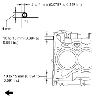
*1 Cylinder Block 
Engine Front Apply seal packing (diameter 4.0 mm (0.157 in.)) to the cylinder block sub-assembly as shown in the illustration.
Seal Packing Toyota Genuine Seal Packing Black, Three Bond 1207B or equivalent Note
Remove any oil from the cylinder block sub-assembly.
-
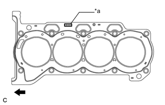
*a Lot No. Engine Front Place a new cylinder head gasket on the cylinder block sub-assembly with the lot No. stamp facing upward.
Note
Install the cylinder head gasket within 3 minutes of applying seal packing.
-
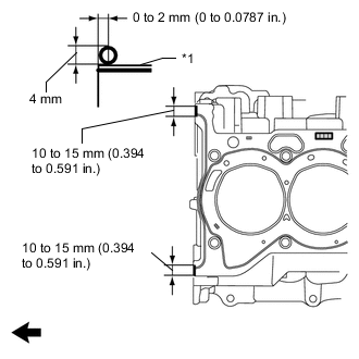
*1 Cylinder Head Gasket Cylinder Block Apply seal packing (diameter 4.0 mm (0.157 in.)) to the new cylinder head gasket as shown in the illustration.
Seal Packing Toyota Genuine Seal Packing Black, Three Bond 1207B or equivalent Note
-
Remove any oil from the cylinder head gasket and cylinder head sub-assembly.
-
Install the cylinder head gasket within 3 minutes and tighten the bolts within 15 minutes of applying seal packing.
-
-
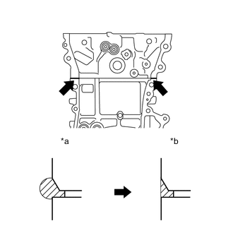
*a Before Wiping Off *b After Wiping Off After tightening the cylinder head set bolts, wipe off any seal packing that seeped out from the contact surfaces between the cylinder head sub-assembly and cylinder block sub-assembly.
-
-
INSTALL CYLINDER HEAD SUB-ASSEMBLY
Tech Tips
The cylinder head set bolts are tightened in 3 progressive steps.
-
Place the cylinder head sub-assembly on the cylinder block sub-assembly.
Note
-
Make sure that no oil is on the mounting surface of the cylinder head sub-assembly.
-
Place the cylinder head sub-assembly on the cylinder block gently in order not to damage the gasket with the bottom of the cylinder head sub-assembly.
-
-
Install the plate washers to the cylinder head set bolts.
-
Apply a light coat of engine oil to the threads and under the heads of the cylinder head set bolts.
-
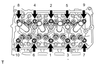
Step 1:
-
Using a 10 mm bi-hexagon wrench, install and uniformly tighten the 10 cylinder head set bolts and 10 plate washers in several steps and in the order shown in the illustration.
- Torque:
- 49 N*m { 500 kgf*cm, 36 ft.*lbf }
Note
Do not drop the plate washers into the cylinder head sub-assembly.
-
-
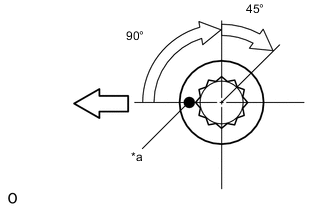
*a Paint Mark 
Engine Front Step 2:
-
Mark the front of each cylinder head set bolt with paint.
-
Tighten the cylinder head set bolts 90° in the order shown in step 1.
-
-
Step 3:
-
Further tighten the cylinder head set bolts by 45° in the order shown in step 1.
-
-
Check that the paint mark is now at a 135° angle to the front.
-
-
INSTALL VALVE STEM CAP
-
INSTALL VALVE LASH ADJUSTER ASSEMBLY
-
INSTALL NO. 1 VALVE ROCKER ARM SUB-ASSEMBLY
-
INSTALL EXHAUST MANIFOLD
-
INSTALL NO. 1 EXHAUST MANIFOLD HEAT INSULATOR
-
INSTALL FUEL INJECTOR ASSEMBLY
-
INSTALL NO. 1 DELIVERY PIPE SPACER
-
INSTALL FUEL DELIVERY PIPE SUB-ASSEMBLY
-
INSTALL CAMSHAFT HOUSING SUB-ASSEMBLY