CAMSHAFT REMOVAL
PROCEDURE
-
REMOVE TIMING CHAIN COVER SUB-ASSEMBLY
-
REMOVE TIMING CHAIN COVER OIL SEAL
-
REMOVE CHAIN TENSIONER SLIPPER
-
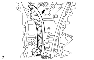
Remove the chain tensioner slipper from the cylinder block.
-
-
REMOVE NO. 1 CHAIN VIBRATION DAMPER
-
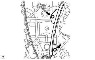
Remove the 2 bolts and No. 1 chain vibration damper.
-
-
REMOVE NO. 2 CHAIN VIBRATION DAMPER
-
Remove the 2 bolts and No. 2 chain vibration damper.
-
-
REMOVE CHAIN SUB-ASSEMBLY
-
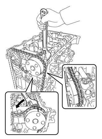
Hold the hexagonal portion of the camshaft with a wrench and turn the camshaft timing gear assembly counterclockwise to loosen the chain sub-assembly between the camshaft timing gear assembly and camshaft timing sprocket.
-
With the chain loosened, release the chain sub-assembly from the camshaft timing gear assembly and place it on the camshaft timing gear assembly.
Tech Tips
Be sure to release the chain sub-assembly from the sprocket completely.
-
Turn the camshaft clockwise to return it to the original position and remove the chain sub-assmbly.
-
-
INSPECT CAMSHAFT TIMING GEAR ASSEMBLY
-
Inspect the lock of the camshaft timing gear assembly.
-
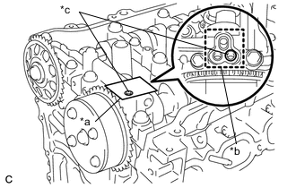
*a Adhesive Tape *b Adhesive Tape Sealing Area *c Prick a Hole After cleaning the VVT oil hole on the intake side of the camshaft bearing cap, completely seal the oil hole with adhesive tape or equivalent as shown in the illustration to prevent air from leaking.
Note
Be sure to cover the oil hole completely because air leaks due to insufficient sealing will prevent the lock pin from being released.
-
Prick a hole in the tape covering the oil hole as shown in the illustration. (Procedure A)
-
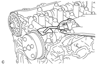
Apply approximately 150 kPa (1.5 kgf/cm2, 22 psi) of air pressure to the hole pricked in procedure A to release the lock pin.
Note
-
If air leaks out, reattach the adhesive tape.
-
Cover the oil hole with a piece of cloth when applying air pressure to prevent oil from spraying.
-
-
Forcibly turn the camshaft timing gear assembly in the advance direction (counterclockwise).
Tech Tips
Depending on the air pressure applied, the camshaft timing gear assembly may turn in the advance direction without assistance.
-
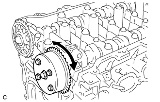
Turn the camshaft timing gear assembly within its movable range (26.5 to 28.5°) 2 or 3 times without turning it to the most retarded position. Make sure that the camshaft timing gear assembly turns smoothly.
-
Remove the adhesive tape from the camshaft bearing cap.
-
-
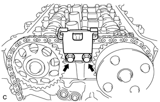
REMOVE CAMSHAFT TIMING GEAR ASSEMBLY
-
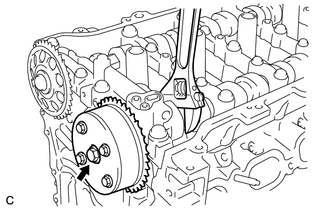
Remove the bolt while holding the hexagonal portion of the camshaft with a wrench, and then remove the camshaft timing gear assembly.
Note
-
Before removing the camshaft timing gear assembly, make sure that the lock pin has been released.
-
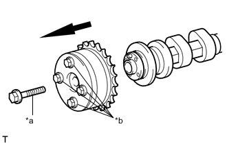
*a Bolt *b Do Not Remove Be sure not to remove the other 4 bolts.
-
Keep the camshaft timing gear assembly horizontal while removing it from the camshaft.
-
-
-
REMOVE CAMSHAFT TIMING SPROCKET
-
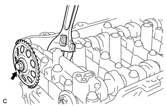
Remove the bolt while holding the hexagonal portion of the camshaft with a wrench, and then remove the camshaft timing sprocket.
-
-
REMOVE CAMSHAFT BEARING CAP
-
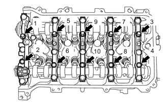
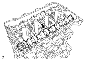
Uniformly loosen and remove the 10 bearing cap bolts in the order shown in the illustration.
-
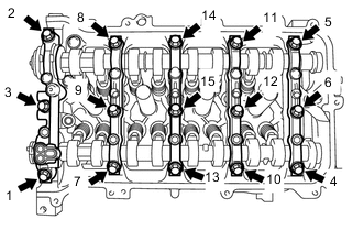
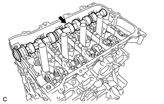
Uniformly loosen and remove the 15 bearing cap bolts in the order shown in the illustration.
Note
Uniformly loosen the bearing cap bolts while keeping the camshaft housing sub-assembly level.
-
Remove the 5 camshaft bearing caps.
Tech Tips
Arrange the removed parts in the correct order.
-
-
REMOVE CAMSHAFT
-
Remove the camshaft.
-
-
REMOVE NO. 2 CAMSHAFT
-
Remove the No. 2 camshaft.
-
-
REMOVE NO. 1 CAMSHAFT BEARING
-
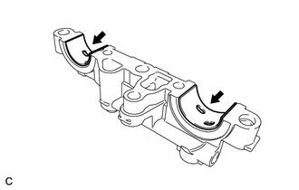
Remove the 2 No. 1 camshaft bearings.
-
-
REMOVE NO. 2 CAMSHAFT BEARING
-
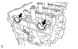
Remove the 2 No. 2 camshaft bearings.
-
-
REMOVE CAMSHAFT HOUSING SUB-ASSEMBLY
-
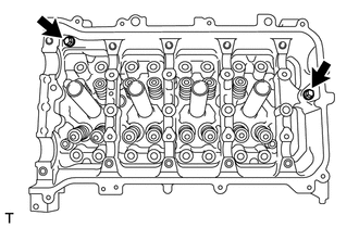
Remove the 2 bolts.
-
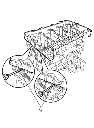
*a Protective Tape Using a screwdriver, remove the camshaft housing sub-assembly by prying between the cylinder head sub-assembly and camshaft housing sub-assembly.
Note
Be careful not to damage the contact surfaces of the cylinder head sub-assembly and camshaft housing sub-assembly.
Tech Tips
Tape the screwdriver tip before use.
-