INVERTER WITH CONVERTER INSTALLATION
PROCEDURE
-
INSTALL NO. 2 ENGINE ROOM WIRE
Tech Tips
Perform this procedure only when replacement of the No. 2 engine room wire is necessary.
-
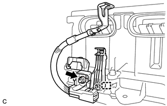
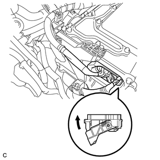
Engage the clamp to Install the No. 2 engine room wire to the inverter with converter assembly.
-
Install the nut to the No. 2 engine room wire.
- Torque:
- 8.0 N*m { 82 kgf*cm, 71 in.*lbf }
-
Engage the 2 claws and close the terminal cover.
-
-
INSTALL HIGH VOLTAGE FUSE
CAUTION:
Wear insulated gloves.
Tech Tips
Perform this procedure only when replacement of the high voltage fuse is necessary.
-
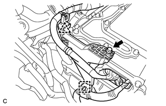
Remove the 9 bolts and inverter cover.
Note
Make sure to pull the inverter cover straight up, as a connector is connected to the bottom of the inverter cover.
-
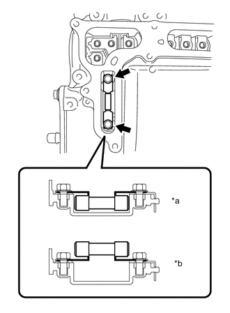
*a Correct *b Incorrect Install the high voltage fuse with the 2 bolts.
- Torque:
- 4.0 N*m { 41 kgf*cm, 35 in.*lbf }
Note
Be sure to use a torque wrench to tighten the bolts.
Note
-
Be sure to use a torque wrench to tighten the bolts.
-
The high voltage fuse should be installed with its orientation as shown in the illustration.
-
Temporarily install the inverter cover with the 9 bolts to prevent any foreign matter or water from entering the inverter with converter assembly.
-
-
INSTALL MOTOR CABLE BRACKET
-
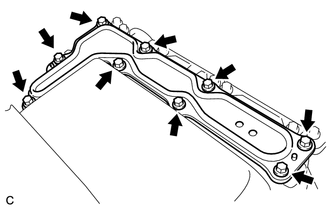
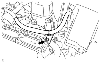
Temporarily install the motor cable bracket with the 2 bolts.
-
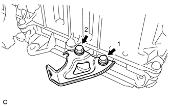
Tighten the 2 bolts in the order shown in the illustration.
- Torque:
- 8.0 N*m { 82 kgf*cm, 71 in.*lbf }
-
-
INSTALL INVERTER WITH CONVERTER ASSEMBLY
CAUTION:
Wear insulated gloves.
-
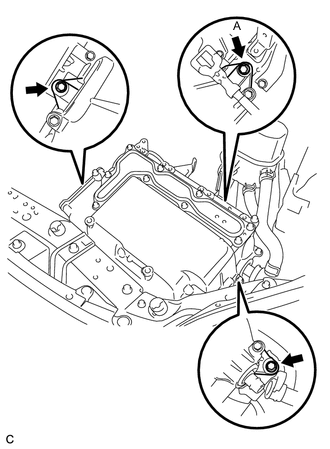
Temporarily install the inverter with converter assembly with the 3 bolts.
Note
-
Since the inverter with converter assembly is very heavy, 2 people are needed to install the inverter with converter assembly. When installing the inverter with converter assembly, do not damage the parts around it.
-
To prevent damage, do not hold the inverter with converter assembly by the connectors.
-
To prevent damage due to static electricity, do not touch the terminals of the disconnected connectors.
-
-
Tighten bolt (A).
- Torque:
- 12 N*m { 122 kgf*cm, 9 ft.*lbf }
-
Tighten the 2 bolts.
- Torque:
- 12 N*m { 122 kgf*cm, 9 ft.*lbf }
-
-
CONNECT NO. 6 INVERTER COOLING HOSE
-
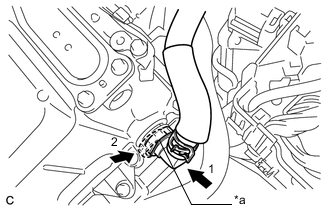
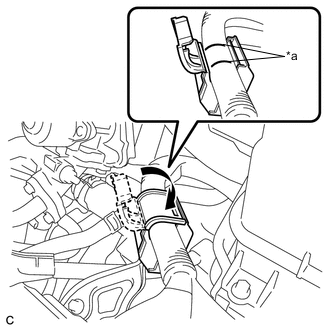
*a Retainer Connect the No. 6 inverter cooling hose to the inverter with converter assembly and lock the hose with the retainer.
Note
-
Insert the retainer until a click sound is heard.
-
Pull on the hose to confirm that the hose is securely connected.
-
If there is foreign matter on the union or the O-ring, clean it with water and finger scouring.
-
To prevent foreign matter from entering the cooling system, do not remove the pieces of cloth or plastic bags from the pipe and disconnected hose until installation.
-
-
-
CONNECT NO. 1 INVERTER COOLING HOSE
-
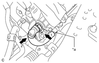
*a Retainer Connect the No. 1 inverter cooling hose to the inverter with converter assembly and lock the hose with the retainer.
Note
-
Insert the retainer until a click sound is heard.
-
Pull on the hose to confirm that the hose is securely connected.
-
If there is foreign matter on the union or the O-ring, clean it with water and finger scouring.
-
To prevent foreign matter from entering the cooling system, do not remove the pieces of cloth or plastic bags from the pipe and disconnected hose until installation.
-
-
-
CONNECT NO. 2 ENGINE ROOM WIRE
-
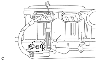
Disconnect the No. 2 engine room wire from the clamp.
-
Connect the No. 2 engine room wire with the bolt and 2 claws.
- Torque:
- 8.5 N*m { 87 kgf*cm, 75 in.*lbf }
-
Engage the 2 claws to install the No. 1 relay block cover.
-
Install the relay block cover.
-
-
REMOVE INVERTER COVER
CAUTION:
Wear insulated gloves.
-
Remove the 9 bolts and inverter cover.
Note
Make sure to pull the inverter cover straight up, as a connector is connected to the bottom of the inverter cover.
-
-
CONNECT NO. 2 ENGINE WIRE
CAUTION:
Wear insulated gloves.
Note
Do not allow any foreign matter or water to enter the inverter with converter assembly.
-
Temporarily install the No. 2 engine wire (high voltage cables of the air conditioning) and 4 bolts to the inverter with converter assembly by hand.
-
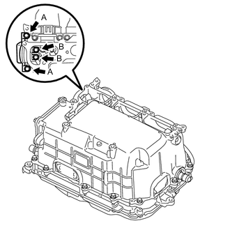
Using an insulated tool, fully tighten the 2 bolts (A).
- Torque:
- 9.2 N*m { 94 kgf*cm, 81 in.*lbf }
Note
Be sure to use a torque wrench to tighten the bolts.
-
Using an insulated tool, fully tighten the 2 bolts (B).
- Torque:
- 8.0 N*m { 82 kgf*cm, 71 in.*lbf }
Note
Be sure to use a torque wrench to tighten the bolts.
-
Connect the harness clamp.
-
-
CONNECT MOTOR CABLE
CAUTION:
Wear insulated gloves.
Note
Do not allow any foreign matter or water to enter the inverter with converter assembly.
-
Temporarily install the high voltage cable of the motor cable (MG2) and 5 bolts to the inverter with converter assembly by hand.
-
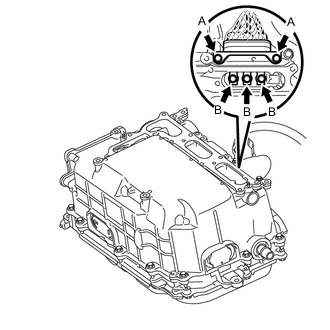
Using an insulated tool, fully tighten the 2 bolts (A).
- Torque:
- 9.2 N*m { 94 kgf*cm, 81 in.*lbf }
Note
Be sure to use a torque wrench to tighten the bolts.
-
Using an insulated tool, fully tighten the 3 bolts (B).
- Torque:
- 8.0 N*m { 82 kgf*cm, 71 in.*lbf }
Note
Be sure to use a torque wrench to tighten the bolts.
-
Connect the harness clamp.
-
-
CONNECT GENERATOR CABLE
CAUTION:
Wear insulated gloves.
Note
Do not allow any foreign matter or water to enter the inverter with converter assembly.
-
Temporarily install the high voltage cable of the generator cable (MG1) and 5 bolts to the inverter with converter assembly by hand.
-
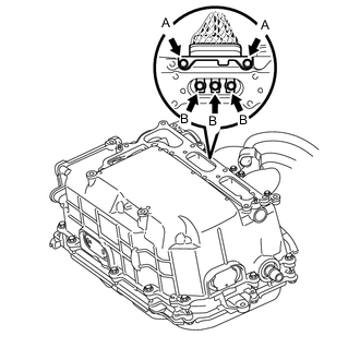
Using an insulated tool, fully tighten the 2 bolts (A).
- Torque:
- 9.2 N*m { 94 kgf*cm, 81 in.*lbf }
Note
Be sure to use a torque wrench to tighten the bolts.
-
Using an insulated tool, fully tighten the 3 bolts (B).
- Torque:
- 8.0 N*m { 82 kgf*cm, 71 in.*lbf }
Note
Be sure to use a torque wrench to tighten the bolts.
-
*a Alignment Mark Install the cable and close the wire harness cover.
Note
Close the cover so that the alignment marks are not visible.
-
-
CONNECT FRAME WIRE
CAUTION:
Wear insulated gloves.
Note
-
Make sure that the interlock is fully engaged.
-
Do not allow any foreign matter or water to enter the inverter with converter assembly.
-
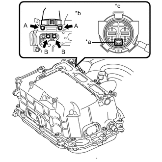
*a Interlock *b High voltage cables of the hybrid battery *c Front view of frame wire connector Temporarily install the frame wire (high voltage cables of the hybrid battery) and 4 bolts to the inverter with converter assembly by hand.
-
Using an insulated tool, fully tighten the 2 bolts (A).
- Torque:
- 9.2 N*m { 94 kgf*cm, 81 in.*lbf }
Note
-
Be sure to use a torque wrench to tighten the bolts.
-
Make sure that the interlock is fully engaged.
-
Using an insulated tool, fully tighten the 2 bolts (B).
- Torque:
- 8.0 N*m { 82 kgf*cm, 71 in.*lbf }
Note
Be sure to use a torque wrench to tighten the bolts.
-
Connect the harness clamp.
-
-
CHECK HIGH VOLTAGE CABLE CONNECTION
CAUTION:
Wear insulated gloves.
Note
Do not allow any foreign matter or water to enter the inverter with converter assembly.
-
Check that each connector and terminal is firmly installed.
Note
Make sure that the bolts are fully tightened.
-
-
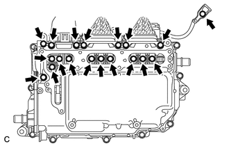
INSTALL INVERTER COVER
CAUTION:
Wear insulated gloves.
Note
-
Make sure that the interlock is fully engaged.
-
Do not allow any foreign matter or water to enter the inverter with converter assembly.
-
*a Interlock Install the inverter cover with the 9 bolts to the inverter with converter assembly.
- Torque:
- 10.7 N*m { 109 kgf*cm, 8 ft.*lbf }
-
-
CONNECT ENGINE ROOM MAIN WIRE
CAUTION:
Wear insulated gloves.
Note
-
Make sure that the connectors are fully engaged.
-
Do not allow any foreign matter or water to enter the inverter with converter assembly.
-
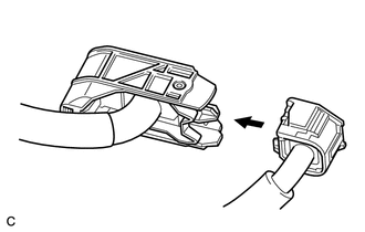
Connect the engine wire to the engine room main wire.
-
Connect the inverter with converter assembly connector to the inverter with converter assembly and lock the connector with the lock lever.
-
Install the bolt, clamp and clip, and connect the engine room main wire.
- Torque:
- 8.0 N*m { 82 kgf*cm, 71 in.*lbf }
-
Install the bolt.
- Torque:
- 8.0 N*m { 82 kgf*cm, 71 in.*lbf }
-
-
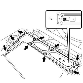
INSTALL NO. 1 INVERTER BRACKET
-
Install the No. 1 inverter bracket with the 3 bolts.
- Torque:
- 13.5 N*m { 138 kgf*cm, 10 ft.*lbf }
-
-
INSTALL SERVICE PLUG GRIP
-
ADD COOLANT (for Inverter)
-
INSPECT FOR COOLANT LEAK (for Inverter)
-
INSTALL NO. 1 ENGINE UNDER COVER