HYBRID BATTERY SYSTEM, Diagnostic DTC:P0A80-123
| DTC Code | DTC Name |
|---|---|
| P0A80-123 | Replace Hybrid Battery Pack |
DESCRIPTION
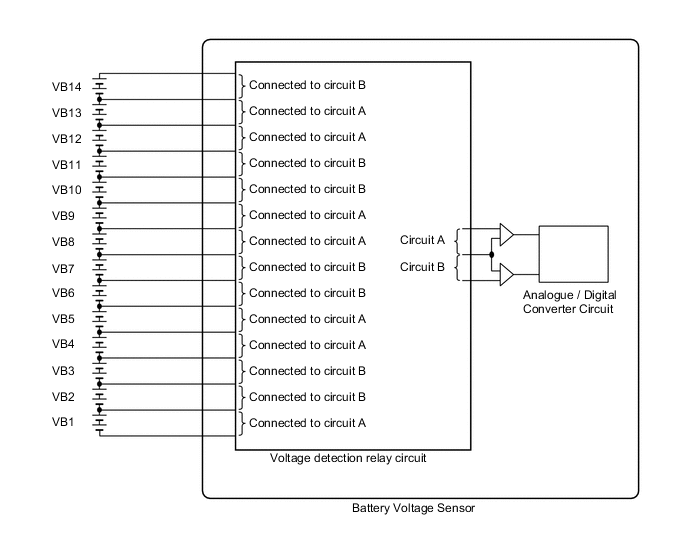
The HV battery uses nickel metal-hydride batteries and does not require external charging. The power management control ECU controls the SOC (state of charge) of the HV battery at a constant level during driving. The HV battery is composed of 28 modules, and each module consists of six 1.2 V cells in series. The battery voltage sensor monitors battery block voltage at 14 locations. Each battery block is composed of 2 modules in a set.
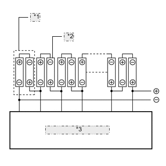
| *1 | Battery Block |
| *2 | Battery Module |
| *3 | Battery Voltage Sensor |
| DTC No. | Detection Item | DTC Detection Condition | Trouble Area | MIL | Warning Indicate |
|---|---|---|---|---|---|
| P0A80-123 | Replace Hybrid Battery Pack | Difference in voltage between battery blocks is larger than the standard (2 trip detection) |
|
Comes on | Comes on |
| Related Data List | ||||
|---|---|---|---|---|
|
Tech Tips
DTC P0A80-123 is stored when a malfunction is detected in the HV battery or battery voltage sensor. If the HV supply battery is malfunctioning, the malfunction may not be reproduced when the condition of the HV supply battery changes due to difference in driving load (amperage), battery SOC and battery temperature. Therefore, use the freeze frame data when performing a repair.
-
When the HV battery is malfunctioning:
-
Voltage of one or a few of the battery blocks has dropped. (voltage difference from that of the next block is 1 V or more)
-
Voltage of all battery blocks is output randomly with no certain pattern.
-
When the battery voltage sensor is malfunctioning:
-
Differences in battery block voltages have a certain pattern.
-
In order to ensure HV battery performance, appropriate cooling performance must be maintained. Perform the following as necessary:
-
Make sure the air intake port is not blocked.
-
Make sure there are no gaps between the connecting parts of the ducts.
INSPECTION PROCEDURE
CAUTION:
When disposing of an HV battery, make sure to return it through an authorized collection agent who is capable of handling it safely. If the HV battery is returned via the manufacturer specified route, it will be returned properly and in a safe manner by an authorized collection agent.
Tech Tips
After the repair, clear the DTCs and perform the following procedure to check that DTCs (including pending DTCs) are not output.
P0A80-123 will not be set unless the vehicle is driven for approximately 10 minutes after clearing the DTCs.
PROCEDURE
-
CHECK DTC OUTPUT (HYBRID CONTROL)
Result Result Proceed to P0AFC-123 is not output. A P0AFC-123 is also output. B
-
Connect the GTS to the DLC3.
-
Turn the power switch on (IG).
-
Enter the following menus: Powertrain / Hybrid Control / Trouble Codes.
-
Read output DTCs.
Result Result Proceed to P0AFC-123 is not output. A P0AFC-123 is also output. B
Powertrain > Hybrid Control > Trouble Codes -
Turn the power switch off.
-
Disconnect the GTS from the DLC3.
B 
GO TO DTC CHART (P0AFC-123) Click here
A 
-
-
CHECK FREEZE FRAME DATA
-
Connect the GTS to the DLC3.
-
Turn the power switch on (IG).
-
Enter the following menus: Powertrain / Hybrid Control / Trouble Codes.
-
Read output DTCs.
Powertrain > Hybrid Control > Trouble Codes -
Using the GTS, make a note of the freeze frame data item "Battery Block Vol - V01 to V14".
-
Compare the freeze frame data item "Battery Block Vol - V01 to V14" values with those shown in the following combination tables.
Table 1 Circuit A Battery Block Circuit B Battery Block Condition Battery Block Vol - V01 (VB1) Battery Block Vol - V02 (VB2) "Battery Block Vol - V01" - "Battery Block Vol - V02" = 0.3 V or more Battery Block Vol - V04 (VB4) Battery Block Vol - V03 (VB3) "Battery Block Vol - V04" - "Battery Block Vol - V03" = 0.3 V or more Battery Block Vol - V05 (VB5) Battery Block Vol - V06 (VB6) "Battery Block Vol - V05" - "Battery Block Vol - V06" = 0.3 V or more Battery Block Vol - V08 (VB8) Battery Block Vol - V07 (VB7) "Battery Block Vol - V08" - "Battery Block Vol - V07" = 0.3 V or more Battery Block Vol - V09 (VB9) Battery Block Vol - V10 (VB10) "Battery Block Vol - V09" - "Battery Block Vol - V10" = 0.3 V or more Battery Block Vol - V12 (VB12) Battery Block Vol - V11 (VB11) "Battery Block Vol - V12" - "Battery Block Vol - V11" = 0.3 V or more Battery Block Vol - V13 (VB13) Battery Block Vol - V14 (VB14) "Battery Block Vol - V13" - "Battery Block Vol - V14" = 0.3 V or more Table 2 Circuit A Battery Block Circuit B Battery Block Condition Battery Block Vol - V01 (VB1) Battery Block Vol - V02 (VB2) "Battery Block Vol - V02" - "Battery Block Vol - V01" = 0.3 V or more Battery Block Vol - V04 (VB4) Battery Block Vol - V03 (VB3) "Battery Block Vol - V03" - "Battery Block Vol - V04" = 0.3 V or more Battery Block Vol - V05 (VB5) Battery Block Vol - V06 (VB6) "Battery Block Vol - V06" - "Battery Block Vol - V05" = 0.3 V or more Battery Block Vol - V08 (VB8) Battery Block Vol - V07 (VB7) "Battery Block Vol - V07" - "Battery Block Vol - V08" = 0.3 V or more Battery Block Vol - V09 (VB9) Battery Block Vol - V10 (VB10) "Battery Block Vol - V10" - "Battery Block Vol - V09" = 0.3 V or more Battery Block Vol - V12 (VB12) Battery Block Vol - V11 (VB11) "Battery Block Vol - V11" - "Battery Block Vol - V12" = 0.3 V or more Battery Block Vol - V13 (VB13) Battery Block Vol - V14 (VB14) "Battery Block Vol - V14" - "Battery Block Vol - V13" = 0.3 V or more 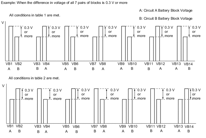
Tech Tips
When an internal malfunction occurs in the battery voltage sensor, this symptom (difference in voltage of 0.3 V or more for all 7 pairs of blocks) will occur.
Result Result Proceed to All conditions in table 1 are met. A All conditions in table 2 are met. Other than above B -
Turn the power switch off.
-
Disconnect the GTS from the DLC3.
A
REPLACE BATTERY VOLTAGE SENSOR Click here
B
REPLACE HV BATTERY Click here
-