HYBRID BATTERY SYSTEM, Diagnostic DTC:P0AC0-123
| DTC Code | DTC Name |
|---|---|
| P0AC0-123 | Hybrid Battery Pack Current Sensor Circuit Range / Performance |
DESCRIPTION
Refer to the description for DTC P0ABF-123.
| DTC No. | Detection Item | DTC Detection Condition | Trouble Area | MIL | Warning Indicate |
|---|---|---|---|---|---|
| P0AC0-123 | Hybrid Battery Pack Current Sensor Circuit Range / Performance | When the battery current sensor is abnormal (1 or 2 trip detection) |
|
Comes on | Comes on |
PROCEDURE
-
CHECK DTC OUTPUT (HYBRID CONTROL)
-
Connect the GTS to the DLC3.
-
Turn the power switch on (IG).
-
Enter the following menus: Powertrain / Hybrid Control / Trouble Codes.
-
Check for and record HV system DTCs, INF codes and freeze frame data.
-
Read the output DTCs.
Powertrain > Hybrid Control > Trouble CodesResult Result Proceed to Only DTC P0AC0-123 is output or DTC P0AC0-123 and DTCs other than those in the following table are output. A Any of the DTCs in the following table are output at the same time. B Relevant DTC P0A95-123 High Voltage Fuse P0ABF-123 Hybrid Battery Pack Current Sensor Circuit P0AC1-123 Hybrid Battery Pack Current Sensor Circuit Low P0AC2-123 Hybrid Battery Pack Current Sensor Circuit High P0AFC-123 Hybrid Battery Pack Sensor Module P0B3D-123, P0B42-123, P0B47-123, P0B4C-123, P0B51-123, P0B56-123, P0B5B-123, P0B60-123, P0B65-123, P0B6A-123, P0B6F-123, P0B74-123, P0B79-123, P0B7E-123, P0B83-123 Hybrid Battery Voltage Sensor "A - O" Circuit Low -
Turn the power switch off.
-
Disconnect the GTS from the DLC3.
B 
GO TO DTC CHART (HYBRID BATTERY SYSTEM) Click here
A 
-
-
READ VALUE USING GTS
-
Connect the GTS to the DLC3.
-
Turn the power switch on (IG).
Note
Do not turn the power switch on (READY).
-
Enter the following menus: Powertrain / Hybrid Control / Data List / Battery Block Vol -V01 to V14.
Powertrain > Hybrid Control > Data ListTester Display Battery Block Vol -V01 Battery Block Vol -V02 Battery Block Vol -V03 Battery Block Vol -V04 Battery Block Vol -V05 Battery Block Vol -V06 Battery Block Vol -V07 Battery Block Vol -V08 Battery Block Vol -V09 Battery Block Vol -V10 Battery Block Vol -V11 Battery Block Vol -V12 Battery Block Vol -V13 Battery Block Vol -V14 Note
Select "Battery Block Vol -V01 to V14" only. (Do not select any other Data List items.)
-
Check the voltage of each "Battery Block Vol" of "Battery Block Vol -V01 to V14" in the Data List with the power switch on (IG).
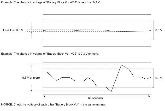
Specified Condition Any "Battery Block Vol" changes by 0.3 V or more 60 seconds after the power switch is turned on (IG). (The difference between the maximum and minimum voltage is 0.3 V or more.) Result Result Proceed to The change in voltage of any "Battery Block Vol" is 0.3 V or more. A Other than above B -
Turn the power switch off.
-
Disconnect the GTS from the DLC3.
A
REPLACE BATTERY VOLTAGE SENSOR Click here
B
REPLACE HV BATTERY JUNCTION BLOCK ASSEMBLY Click here
-