HYBRID CONTROL SYSTEM, Diagnostic DTC:P3108-536
| DTC Code | DTC Name |
|---|---|
| P3108-536 | Lost Communication with A/C System Control Module |
DESCRIPTION
The hybrid vehicle control ECU assembly detects a wiring malfunction in the serial communication line between it and the compressor with motor assembly.
| DTC No. | Detection Item | DTC Detection Condition | Trouble Area | MIL | Warning Indicate |
|---|---|---|---|---|---|
| P3108-536 | Lost Communication with A/C System Control Module | A/C inverter malfunction |
|
Does not come on | Master Warning Light: Does not come on |
WIRING DIAGRAM
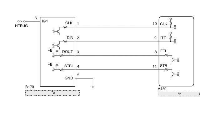
| *a | Compressor with Motor Assembly |
| *b | Hybrid Vehicle Control ECU Assembly |
PROCEDURE
-
CHECK DTC OUTPUT (AIR CONDITIONING SYSTEM)
-
Connect the GTS to the DLC3.
-
Turn the power switch on (IG).
-
Enter the following menus: Body Electrical / Air Conditioner / Trouble Codes.
-
Check for DTCs.
Body Electrical > Air Conditioner > Trouble CodesResult Result Proceed to DTCs related to A/C are not output. A DTCs related to A/C are output. B -
Turn the power switch off.
B 
GO TO DTC CHART (AIR CONDITIONING SYSTEM) Click here
A 
-
-
CHECK CONNECTOR CONNECTION CONDITION (HYBRID VEHICLE CONTROL ECU ASSEMBLY CONNECTOR)
Result Proceed to OK NG
-
Check the connector connections and contact pressure of the relevant terminals for the hybrid vehicle control ECU assembly connectors.
OK The connectors are connected securely and there are no contact pressure problems. 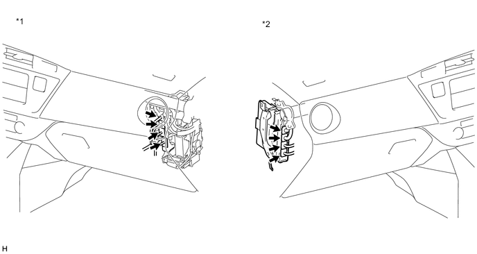
*1 for LHD *2 for RHD Result Proceed to OK NG
NG
CONNECT SECURELY
OK
-
-
CHECK CONNECTOR CONNECTION CONDITION (COMPRESSOR WITH MOTOR ASSEMBLY CONNECTOR)
-
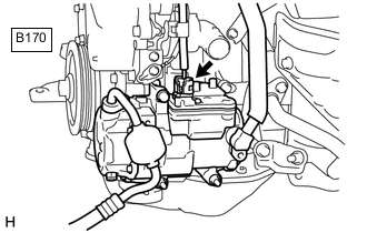
Check the connection of the B170 compressor with motor assembly connector.
OK The connector is connected securely and there are no contact problems. Result Proceed to OK NG
NG
CONNECT SECURELY
OK
-
-
CHECK HARNESS AND CONNECTOR (COMPRESSOR WITH MOTOR ASSEMBLY POWER SOURCE CIRCUIT)
-
Disconnect the B170 compressor with motor assembly connector.
-
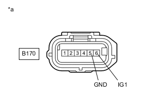
*a Front view of wire harness connector
(to Compressor with Motor Assembly)
Measure the resistance according to the value(s) in the table below.
Standard Resistance Tester Connection Condition Specified Condition B170-5 (GND) - Body ground Power switch off Below 1 Ω -
Turn the power switch on (IG).
-
Measure the voltage according to the value(s) in the table below.
Standard Voltage Tester Connection Condition Specified Condition B170-6 (IG1) - B170-5 (GND) Power switch on (IG) 11 to 14 V Note
Turning the power switch on (IG) with the compressor with motor assembly connector disconnected causes other DTCs to be stored. Clear the DTCs after performing this inspection.
-
Turn the power switch off.
-
Reconnect the B170 compressor with motor assembly connector.
Result Proceed to OK NG
NG
REPAIR OR REPLACE HARNESS OR CONNECTOR
OK
-
-
CHECK HARNESS AND CONNECTOR (HYBRID VEHICLE CONTROL ECU ASSEMBLY - COMPRESSOR WITH MOTOR ASSEMBLY)
-
Disconnect the A150 hybrid vehicle control ECU assembly connector.
-
Disconnect the B170 compressor with motor assembly connector.
-
Turn the power switch on (IG).
-
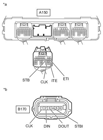
*a Rear view of wire harness connector
(to Hybrid Vehicle Control ECU Assembly)
*b Front view of wire harness connector
(to Compressor with Motor Assembly)
Measure the voltage according to the value(s) in the table below.
Standard Voltage Tester Connection Condition Specified Condition A150-10 (CLK) - Body ground Power switch on (IG) Below 1 V A150-8 (ETI) - Body ground Power switch on (IG) Below 1 V A150-9 (ITE) - Body ground Power switch on (IG) Below 1 V A150-11 (STB) - Body ground Power switch on (IG) Below 1 V Note
Turning the power switch on (IG) with the hybrid vehicle control ECU assembly connector and the compressor with motor assembly connector disconnected causes other DTCs to be stored. Clear the DTCs after performing this inspection.
-
Turn the power switch off.
-
Measure the resistance according to the value(s) in the table below.
Standard Resistance (Check for Open) Tester Connection Condition Specified Condition A150-10 (CLK) - B170-1 (CLK) Power switch off Below 1 Ω A150-8 (ETI) - B170-3 (DOUT) Power switch off Below 1 Ω A150-9 (ITE) - B170-2 (DIN) Power switch off Below 1 Ω A150-11 (STB) - B170-4 (STBI) Power switch off Below 1 Ω Standard Resistance (Check for Short) Tester Connection Condition Specified Condition A150-10 (CLK) or B170-1 (CLK) - Body ground and other terminals Power switch off 10 kΩ or higher A150-8 (ETI) or B170-3 (DOUT) - Body ground and other terminals Power switch off 10 kΩ or higher A150-9 (ITE) or B170-2 (DIN) - Body ground and other terminals Power switch off 10 kΩ or higher A150-11 (STB) or B170-4 (STBI) - Body ground and other terminals Power switch off 10 kΩ or higher -
Reconnect the B170 compressor with motor assembly connector.
-
Reconnect the A150 hybrid vehicle control ECU assembly connector.
Result Proceed to OK NG
NG
REPAIR OR REPLACE HARNESS OR CONNECTOR
OK
-
-
CHECK HYBRID VEHICLE CONTROL ECU ASSEMBLY
-
Disconnect the B170 compressor with motor assembly connector.
-
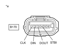
*a Front view of wire harness connector
(to Compressor with Motor Assembly)
Measure the resistance according to the value(s) in the table below.
Standard Resistance Tester Connection Condition Specified Condition B170-3 (DOUT) - Body ground Power switch off 10 kΩ or higher B170-4 (STBI) - Body ground Power switch off 10 kΩ or higher -
Turn the power switch on (IG).
-
Measure the voltage according to the value(s) in the table below.
Standard Voltage Tester Connection Condition Specified Condition B170-1 (CLK) - Body ground Power switch on (IG) 11 to 14 V B170-2 (DIN) - Body ground Power switch on (IG) 11 to 14 V B170-3 (DOUT) - Body ground Power switch on (IG) Below 1 V B170-4 (STBI) - Body ground Power switch on (IG) Below 1 V Note
Turning the power switch on (IG) with the compressor with motor assembly connector disconnected causes other DTCs to be stored. Clear the DTCs after performing this inspection.
-
Turn the power switch off.
-
Reconnect the B170 compressor with motor assembly connector.
Result Proceed to OK NG
NG
REPLACE HYBRID VEHICLE CONTROL ECU ASSEMBLY for LHD: Click here
REPLACE HYBRID VEHICLE CONTROL ECU ASSEMBLY for RHD: Click hereOK
-
-
CHECK COMPRESSOR WITH MOTOR ASSEMBLY
-
Disconnect the A150 hybrid vehicle control ECU assembly connector.
-
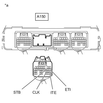
*a Rear view of wire harness connector
(to Hybrid Vehicle Control ECU Assembly)
Measure the resistance according to the value(s) in the table below.
Standard Resistance Tester Connection Condition Specified Condition A150-10 (CLK) - Body ground Power switch off 10 kΩ or higher A150-9 (ITE) - Body ground Power switch off 10 kΩ or higher -
Turn the power switch on (IG).
-
Measure the voltage according to the value(s) in the table below.
Standard Voltage Tester Connection Condition Specified Condition A150-10 (CLK) - Body ground Power switch on (IG) Below 1 V A150-8 (ETI) - Body ground Power switch on (IG) 11 to 14 V A150-9 (ITE) - Body ground Power switch on (IG) Below 1 V A150-11 (STB) - Body ground Power switch on (IG) 11 to 14 V Note
Turning the power switch on (IG) with the hybrid vehicle control ECU assembly connector disconnected causes other DTCs to be stored. Clear the DTCs after performing this inspection.
-
Turn the power switch off.
-
Reconnect the A150 hybrid vehicle control ECU assembly connector.
Result Proceed to OK NG
OK
REPLACE HYBRID VEHICLE CONTROL ECU ASSEMBLY for LHD: Click here
REPLACE HYBRID VEHICLE CONTROL ECU ASSEMBLY for RHD: Click hereNG
REPLACE COMPRESSOR WITH MOTOR ASSEMBLY Click here
-