HYBRID CONTROL SYSTEM, Diagnostic DTC:P0A78-286
| DTC Code | DTC Name |
|---|---|
| P0A78-286 | Drive Motor "A" Inverter Performance |
DESCRIPTION
For a description of the inverter.
If the motor inverter overheats, has a circuit malfunction, or has an internal short, the inverter transmits this information to the MG ECU via the motor inverter fail signal line.
Tech Tips
The term "drive motor A" indicates MG2.
| DTC No. | Detection Item | DTC Detection Condition | Trouble Area | MIL | Warning Indicate |
|---|---|---|---|---|---|
| P0A78-286 | Drive Motor "A" Inverter Performance | Motor inverter fail signal detection (circuit malfunction) |
|
Comes on | Master Warning Light: Comes on |
WIRING DIAGRAM
Refer to the wiring diagram for DTC P1CAC-200.
Refer to the wiring diagram for DTC P0AA6-526.
Refer to the wiring diagram for DTC P324E-788.
Refer to the wiring diagram for DTC U0110-159.
CAUTION / NOTICE / HINT
CAUTION:
-
Before inspecting the high-voltage system or disconnecting the low voltage connector of the inverter with converter assembly, take safety precautions such as wearing insulated gloves and removing the service plug grip to prevent electrical shocks. After removing the service plug grip, put it in your pocket to prevent other technicians from accidentally reconnecting it while you are working on the high-voltage system.
-
After removing the service plug grip, wait for at least 10 minutes before touching any of the high-voltage connectors or terminals. After waiting for 10 minutes, check the voltage at the terminals in the inspection point in the inverter with converter assembly. The voltage should be 0 V before beginning work.
Tech Tips
Waiting for at least 10 minutes is required to discharge the high-voltage capacitor inside the inverter with converter assembly.
Note
After turning the power switch off, waiting time may be required before disconnecting the cable from the negative (-) auxiliary battery terminal. Therefore, make sure to read the disconnecting the cable from the negative (-) auxiliary battery terminal notices before proceeding with work.
PROCEDURE
-
CHECK DTC OUTPUT (HYBRID CONTROL)
-
Connect the GTS to the DLC3.
-
Turn the power switch on (IG).
-
Enter the following menus: Powertrain / Hybrid Control / Trouble Codes.
-
Check for DTCs.
Powertrain > Hybrid Control > Trouble CodesResult Result Proceed to P0A78-202 is not output. A P0A78-202 is also output. B Note
-
If P0A78-202 is output, troubleshoot it first. After completing the troubleshooting for P0A78-202, perform troubleshooting for this DTC.
-
Parts repaired or replaced during troubleshooting for P0A78-202 do not need to be re-inspected in this diagnosis procedure.
-
-
Turn the power switch off.
B 
GO TO DTC CHART (P0A78-202) Click here
A 
-
-
CHECK DTC OUTPUT (HYBRID CONTROL)
-
Connect the GTS to the DLC3.
-
Turn the power switch on (IG).
-
Enter the following menus: Powertrain / Hybrid Control / Trouble Codes.
-
Check for DTCs.
Powertrain > Hybrid Control > Trouble CodesTech Tips
-
If P0A78-202 was not output in step 1 of this diagnosis procedure, check Table 1 below.
-
If P0A78-202 was output in step 1 of this diagnosis procedure, diagnose that DTC first, then check Table 2 below.
Result Result Proceed to P0A78-286 only is output, or DTCs except the ones in the tables below are also output. A Any of the following DTCs are also output. B Table 1 DTC No. Relevant Diagnosis P06B0-163 Sensor Power Supply "A" Circuit / Open P06D6-511 Sensor Reference Voltage "F" Circuit / Open P06E6-164 Sensor Power Supply "C" Circuit / Open P0A1A-151, 166, 517, 658, 791, 809 Generator Control Module P0A1B-198, 503, 505, 547, 554, 786, 794, 806 Drive Motor "A" Control Module P0A1D (all INF codes)*1 Hybrid Powertrain Control Module P0A3F-243 Drive Motor "A" Position Sensor Circuit P0A40-500, 504, 506, 549, 556, 808 Drive Motor "A" Position Sensor Circuit Range / Performance P0A41-245 Drive Motor "A" Position Sensor Circuit Low P0A4B-253 Generator Position Sensor Circuit P0A4C-513, 518, 811 Generator Position Sensor Circuit Range / Performance P0A4D-255 Generator Position Sensor Circuit Low P0A78-113, 128, 279, 284, 287, 548, 555, 807 Drive Motor "A" Inverter Performance P0A7A-122, 130, 322, 325, 810 Generator Inverter Performance P0A90-509 Drive Motor "A" Performance P0A92-521 Hybrid Generator Performance P0BEA-290 Drive Motor "A" Phase V Current Sensor Circuit Range / Performance P0BEE-298 Drive Motor "A" Phase W Current Sensor Circuit Range / Performance P0C19-306 Drive Motor "A" Torque Delivered Performance P0C73-776 Motor Electronics Coolant Pump "A" Control Performance P0C76-523 Hybrid Battery System Discharge Time Too Long P0CA3-442 DC/DC Converter Step Up Voltage Performance P0D2E-586 Drive Motor "A" Inverter Voltage Sensor Circuit Range / Performance P0D2F-266 Drive Motor "A" Inverter Voltage Sensor Circuit Low P0D30-267 Drive Motor "A" Inverter Voltage Sensor Circuit High P0E05-328 Generator Phase V Current Sensor Circuit Range / Performance P0E09-336 Generator Phase W Current Sensor Circuit Range / Performance P0E32-585 DC/DC Converter Voltage Sensor "A" Range / Performance P0E33-589 DC/DC Converter Voltage Sensor "A" Low P0E34-590 DC/DC Converter Voltage Sensor "A" High P0E71-344 Generator Torque Delivered Performance P1C2A-155 Generator A/D Converter Circuit P1C2B-192 Drive Motor "A" A/D Converter Circuit P1C2D-587 Hybrid Battery Voltage / DC/DC Converter Voltage Correlation P1C3C-294 Drive Motor "A" Phase V Current Sensor Correlation P1C3D-302 Drive Motor "A" Phase W Current Sensor Correlation P1C3E-333 Generator Phase V Current Sensor Correlation P1C3F-341 Generator Phase W Current Sensor Correlation P1C4A-288 Drive Motor "A" Phase V Current Sensor Sub Circuit Range / Performance P1C4F-296 Drive Motor "A" Phase W Current Sensor Sub Circuit Range / Performance P1C54-326 Generator Phase V Current Sensor Sub Circuit Range / Performance P1C59-334 Generator Phase W Current Sensor Sub Circuit Range / Performance P1C6D-501 Drive Motor "A" Phase V Current Sensor Offset Range / Performance P1C6E-502 Drive Motor "A" Phase W Current Sensor Offset Range / Performance P1C71-515 Generator Phase V Current Sensor Offset Range / Performance P1C72-516 Generator Phase W Current Sensor Offset Range / Performance P1C73-512 Sensor Standard Voltage "F" Circuit / Open P1CA6-156 Generator Control Module Malfunction P1CA7-193 Drive Motor Control Module Malfunction P1CAC-200 Generator Position Sensor Angle Malfunction P1CAD-168 Drive Motor "A" Position Sensor Angle Malfunction P1CAF-792 Generator Position Sensor REF Signal Cycle Malfunction P1CB0-795 Drive Motor "A" Position Sensor REF Signal Cycle Malfunction P1CB2-793 Generator Position Sensor REF Signal Stop Malfunction P1CB3-796 Drive Motor "A" Position Sensor REF Signal Stop Malfunction P3133-659 Communication Error from Generator to Drive Motor "A" P3134-661 Communication Error from Drive Motor "A" to Generator P314A-828 Inverter Coolant Pump Speed Signal Table 2 DTC No. Relevant Diagnosis P06B0-163 Sensor Power Supply "A" Circuit / Open P06D6-511 Sensor Reference Voltage "F" Circuit / Open P06E6-164 Sensor Power Supply "C" Circuit / Open P0A1A-151, 166, 517, 658, 791, 809 Generator Control Module P0A1B-198, 503, 505, 547, 554, 786, 794, 806 Drive Motor "A" Control Module P0A1D (all INF codes)*1 Hybrid Powertrain Control Module P0A3F-243 Drive Motor "A" Position Sensor Circuit P0A40-500, 504, 506, 549, 556, 808 Drive Motor "A" Position Sensor Circuit Range / Performance P0A41-245 Drive Motor "A" Position Sensor Circuit Low P0A4B-253 Generator Position Sensor Circuit P0A4C-513, 518, 811 Generator Position Sensor Circuit Range / Performance P0A4D-255 Generator Position Sensor Circuit Low P0A78-113, 128, 279, 284, 287, 548, 555, 807 Drive Motor "A" Inverter Performance P0A7A-122, 130, 322, 325, 810 Generator Inverter Performance P0A92-521 Hybrid Generator Performance P0C73-776 Motor Electronics Coolant Pump "A" Control Performance P0C76-523 Hybrid Battery System Discharge Time Too Long P0CA3-442 DC/DC Converter Step Up Voltage Performance P0D2E-586 Drive Motor "A" Inverter Voltage Sensor Circuit Range / Performance P0D2F-266 Drive Motor "A" Inverter Voltage Sensor Circuit Low P0D30-267 Drive Motor "A" Inverter Voltage Sensor Circuit High P0E05-328 Generator Phase V Current Sensor Circuit Range / Performance P0E09-336 Generator Phase W Current Sensor Circuit Range / Performance P0E32-585 DC/DC Converter Voltage Sensor "A" Range / Performance P0E33-589 DC/DC Converter Voltage Sensor "A" Low P0E34-590 DC/DC Converter Voltage Sensor "A" High P0E71-344 Generator Torque Delivered Performance P1C2A-155 Generator A/D Converter Circuit P1C2B-192 Drive Motor "A" A/D Converter Circuit P1C2D-587 Hybrid Battery Voltage / DC/DC Converter Voltage Correlation P1C3C-294 Drive Motor "A" Phase V Current Sensor Correlation P1C3D-302 Drive Motor "A" Phase W Current Sensor Correlation P1C3E-333 Generator Phase V Current Sensor Correlation P1C3F-341 Generator Phase W Current Sensor Correlation P1C54-326 Generator Phase V Current Sensor Sub Circuit Range / Performance P1C59-334 Generator Phase W Current Sensor Sub Circuit Range / Performance P1C71-515 Generator Phase V Current Sensor Offset Range / Performance P1C72-516 Generator Phase W Current Sensor Offset Range / Performance P1C73-512 Sensor Standard Voltage "F" Circuit / Open P1CA6-156 Generator Control Module Malfunction P1CA7-193 Drive Motor Control Module Malfunction P1CAC-200 Generator Position Sensor Angle Malfunction P1CAD-168 Drive Motor "A" Position Sensor Angle Malfunction P1CAF-792 Generator Position Sensor REF Signal Cycle Malfunction P1CB0-795 Drive Motor "A" Position Sensor REF Signal Cycle Malfunction P1CB2-793 Generator Position Sensor REF Signal Stop Malfunction P1CB3-796 Drive Motor "A" Position Sensor REF Signal Stop Malfunction P3133-659 Communication Error from Generator to Drive Motor "A" P3134-661 Communication Error from Drive Motor "A" to Generator P314A-828 Inverter Coolant Pump Speed Signal Tech Tips
-
*1: If any INF codes are output for this DTC, refer to the corresponding diagnostic procedure.
-
P0A78-286 may be stored due to a malfunction which also causes DTCs in the preceding tables to be stored. In this case, first troubleshoot the output DTCs in the preceding tables.
-
-
Turn the power switch off.
B
GO TO DTC CHART (HYBRID CONTROL SYSTEM) Click here
A
-
-
CHECK CONNECTOR CONNECTION CONDITION (INVERTER WITH CONVERTER ASSEMBLY CONNECTOR)
Result Proceed to OK NG CAUTION:
Be sure to wear insulated gloves.
-
Check that the service plug grip is not installed.
Note
After removing the service plug grip, do not turn the power switch on (READY), unless instructed by the repair manual because this may cause a malfunction.
-
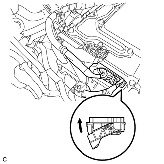
Check the connector connections and contact pressure of the low voltage connectors of the inverter with converter assembly.
Note
Before disconnecting the connector, confirm that it is properly connected by checking that the locking claws are engaged and that the connector does not pull out.
OK The connectors are connected securely and there are no contact pressure problems. Tech Tips
When connecting the connector, insert it with the locking lever in the raised position. Rotate the lever downward and make sure that the connector is pulled into its socket. When the locking lever is in its fully closed position, a click will be heard as its locking claws engage. After the click is heard, pull up on the connector to confirm that it is properly connected.
Result Proceed to OK NG
NG
CONNECT SECURELY
OK
-
-
CHECK QUANTITY OF HV COOLANT
Result Proceed to A B C
-
Check the HV coolant level in the inverter reserve tank.
-
Check for HV coolant leaks.
Result Result Proceed to No leaks are found and coolant level in the inverter reserve tank assembly is above the low line. A No leaks are found and coolant level in the inverter reserve tank assembly is below the low line. B HV coolant leaks are evident. C Tech Tips
After repairing the HV coolant leaks and adding coolant, perform the "Activate the (Inverter) Water Pump" Active Test (HV Active Test item) and the "Control the Electric Cooling Fan" Active Test (Engine Active Test item) and make sure that there are no malfunctions.
B
ADD HV COOLANT
C
INSPECT FOR HV COOLANT LEAK AND ADD HV COOLANT
A
-
-
CHECK COOLANT HOSE
Result Proceed to OK NG
-
Check if the hoses of the cooling system are kinked or clogged.
Result Proceed to OK NG
NG
CORRECT THE PROBLEM
OK
-
-
PERFORM ACTIVE TEST USING GTS (CONTROL THE ELECTRIC COOLING FAN)
Result Proceed to OK NG
-
Connect the GTS to the DLC3.
-
Turn the power switch on (IG).
-
Enter the following menus: Powertrain / Engine and ECT / Active Test / Control the Electric Cooling Fan.
Powertrain > Engine and ECT > Active TestTester Display Control the Electric Cooling Fan -
Perform the "Control the Electric Cooling Fan" Active Test.
OK The cooling fan rotates. -
Turn the power switch off.
Result Proceed to OK NG
NG
CHECK COOLING FAN SYSTEM Click here
OK
-
-
CHECK HV COOLANT (CHECK FOR CONDITIONS THAT MAY HAVE CAUSED FREEZING)
Result Proceed to A B
-
Connect the GTS to the DLC3.
-
Turn the power switch on (IG).
-
Enter the following menus: Powertrain / Hybrid Control / Trouble Codes.
-
Read the freeze frame data Ambient Temperature using the GTS.
Powertrain > Hybrid Control > Trouble Codes -
Check if the freeze frame data Ambient Temperature is below freezing the freezing temperature of the HV coolant.
Result Result Proceed to Ambient Temperature value is below freezing temperature of the HV coolant. A Ambient Temperature value is above freezing temperature of the HV coolant. B Tech Tips
-
HV coolant (SLLC) with a 30% concentration freezes at -15 °C (5°F) and HV coolant (SLLC) with a 50% concentration freezes at -35°C (-31°F).
-
If the HV coolant freezes in the HV radiator or HV water pump, the coolant temperature in the inverter with converter assembly rises because the HV coolant cannot circulate. As a result, a DTC may be stored.
-
A DTC is stored when the water pump impeller cannot rotate due to freezing of the HV coolant.
-
If a DTC is stored due to freezing of HV coolant, the problem cannot be reproduced. Judge whether freezing of HV coolant occurred according to the freeze point of the HV coolant, HV coolant change history and ambient temperature when the DTC was stored.
-
-
Turn the power switch off.
B 
REPLACE HV COOLANT Click here
A
-
-
CHECK HARNESS AND CONNECTOR (INVERTER WITH CONVERTER ASSEMBLY - GENERATOR RESOLVER)
Result Proceed to OK NG CAUTION:
Be sure to wear insulated gloves.
-
Check that the service plug grip is not installed.
Note
After removing the service plug grip, do not turn the power switch on (READY), unless instructed by the repair manual because this may cause a malfunction.
-
Disconnect the B179 inverter with converter assembly connector.
-
Connect the cable to the negative (-) auxiliary battery terminal.
-
Turn the power switch on (IG).
-
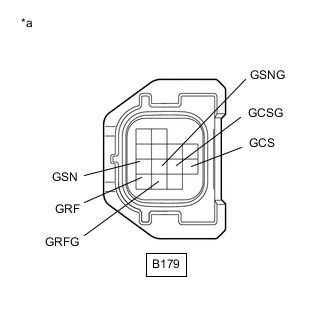
*a Front view of wire harness connector
(to Inverter with Converter Assembly)
Measure the voltage according to the value(s) in the table below.
Standard Voltage Tester Connection Condition Specified Condition B179-11 (GRF) - Body ground Power switch on (IG) Below 1 V B179-12 (GRFG) - Body ground Power switch on (IG) Below 1 V B179-7 (GSN) - Body ground Power switch on (IG) Below 1 V B179-8 (GSNG) - Body ground Power switch on (IG) Below 1 V B179-10 (GCS) - Body ground Power switch on (IG) Below 1 V B179-9 (GCSG) - Body ground Power switch on (IG) Below 1 V Note
Turning the power switch on (IG) with the inverter with converter assembly disconnected causes other DTCs to be stored. Clear the DTCs after performing this inspection.
-
Turn the power switch off.
-
Disconnect the cable from the negative (-) auxiliary battery terminal.
-
Reconnect the B179 inverter with converter assembly connector.
Result Proceed to OK NG
NG
REPAIR OR REPLACE HARNESS OR CONNECTOR
OK
-
-
CHECK GENERATOR RESOLVER
Result Proceed to OK NG CAUTION:
Be sure to wear insulated gloves.
-
Check that the service plug grip is not installed.
Note
After removing the service plug grip, do not turn the power switch on (READY), unless instructed by the repair manual because this may cause a malfunction.
-
Disconnect the B179 inverter with converter assembly connector.
-
*a Front view of wire harness connector
(to Inverter with Converter Assembly)
Measure the resistance according to the value(s) in the table below.
Standard Resistance (Check for Open) Tester Connection Condition Specified Condition B179-11 (GRF) - B179-12 (GRFG) Power switch off 7.1 to 21.6 Ω B179-7 (GSN) - B179-8 (GSNG) Power switch off 13.7 to 34.5 Ω B179-10 (GCS) - B179-9 (GCSG) Power switch off 12.8 to 32.4 Ω Standard Resistance (Check for Short) Tester Connection Condition Specified Condition B179-11 (GRF) or B179-12 (GRFG) - Body ground and other terminals Power switch off 1 MΩ or higher B179-7 (GSN) or B179-8 (GSNG) - Body ground and other terminals Power switch off 1 MΩ or higher B179-10 (GCS) or B179-9 (GCSG) - Body ground and other terminals Power switch off 1 MΩ or higher -
Reconnect the B179 inverter with converter assembly connector.
Result Proceed to OK NG
NG
CHECK CONNECTOR CONNECTION CONDITION (GENERATOR RESOLVER CONNECTOR) Click here
OK
-
-
CHECK HARNESS AND CONNECTOR (INVERTER WITH CONVERTER ASSEMBLY - MOTOR RESOLVER)
Result Proceed to OK NG CAUTION:
Be sure to wear insulated gloves.
-
Check that the service plug grip is not installed.
Note
After removing the service plug grip, do not turn the power switch on (READY), unless instructed by the repair manual because this may cause a malfunction.
-
Disconnect the B179 inverter with converter assembly connector.
-
Connect the cable to the negative (-) auxiliary battery terminal.
-
Turn the power switch on (IG).
-
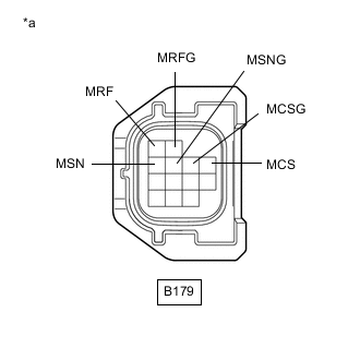
*a Front view of wire harness connector
(to Inverter with Converter Assembly)
Measure the voltage according to the value(s) in the table below.
Standard Voltage Tester Connection Condition Specified Condition B179-1 (MRF) - Body ground Power switch on (IG) Below 1 V B179-2 (MRFG) - Body ground Power switch on (IG) Below 1 V B179-3 (MSN) - Body ground Power switch on (IG) Below 1 V B179-4 (MSNG) - Body ground Power switch on (IG) Below 1 V B179-6 (MCS) - Body ground Power switch on (IG) Below 1 V B179-5 (MCSG) - Body ground Power switch on (IG) Below 1 V Note
Turning the power switch on (IG) with the inverter with converter assembly disconnected causes other DTCs to be stored. Clear the DTCs after performing this inspection.
-
Turn the power switch off.
-
Disconnect the cable from the negative (-) auxiliary battery terminal.
-
Reconnect the B179 inverter with converter assembly connector.
Result Proceed to OK NG
NG
REPAIR OR REPLACE HARNESS OR CONNECTOR
OK
-
-
CHECK MOTOR RESOLVER
Result Proceed to OK NG CAUTION:
Be sure to wear insulated gloves.
-
Check that the service plug grip is not installed.
Note
After removing the service plug grip, do not turn the power switch on (READY), unless instructed by the repair manual because this may cause a malfunction.
-
Disconnect the B179 inverter with converter assembly connector.
-
*a Front view of wire harness connector
(to Inverter with Converter Assembly)
Measure the resistance according to the value(s) in the table below.
Standard Resistance (Check for Open) Tester Connection Condition Specified Condition B179-1 (MRF) - B179-2 (MRFG) Power switch off 7.1 to 21.6 Ω B179-3 (MSN) - B179-4 (MSNG) Power switch off 13.7 to 34.5 Ω B179-6 (MCS) - B179-5 (MCSG) Power switch off 12.8 to 32.4 Ω Standard Resistance (Check for Short) Tester Connection Condition Specified Condition B179-1 (MRF) or B179-2 (MRFG) - Body ground and other terminals Power switch off 1 MΩ or higher B179-3 (MSN) or B179-4 (MSNG) - Body ground and other terminals Power switch off 1 MΩ or higher B179-6 (MCS) or B179-5 (MCSG) - Body ground and other terminals Power switch off 1 MΩ or higher -
Reconnect the B179 inverter with converter assembly connector.
Result Proceed to OK NG
NG
CHECK CONNECTOR CONNECTION CONDITION (MOTOR RESOLVER CONNECTOR) Click here
OK
-
-
CHECK INVERTER WITH CONVERTER ASSEMBLY (GENERATOR CABLE CONNECTION CONDITION)
Result Proceed to A B C CAUTION:
Be sure to wear insulated gloves.
-
Check that the service plug grip is not installed.
Note
After removing the service plug grip, do not turn the power switch on (READY), unless instructed by the repair manual because this may cause a malfunction.
-
Remove the inverter cover from the inverter with converter assembly.
-
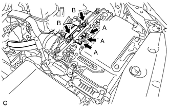
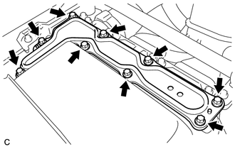
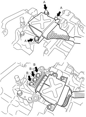
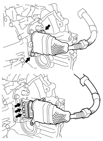
Check that the bolts for the generator cable are tightened to the specified torque, the generator cable is connected securely, and there are no contact problems.
Specified Condition Bolt A T = 8.0 N*m (82 kgf*cm, 71 in.*lbf) Bolt B T = 9.2 N*m (94 kgf*cm, 81 in.*lbf) Note
-
Make sure that the tightening torque of the bolt A is between 6.4 and 9.6 N*m (65 and 98 kgf*cm, 57 and 85 in.*lbf).
-
Make sure that the tightening torque of the bolt B is between 6.4 and 12 N*m (65 and 122 kgf*cm, 57 and 106 in.*lbf).
-
-
Disconnect the generator cable from the inverter with converter assembly.
-
Check for arc marks at the terminals for the generator cable.
Result Result Proceed to The terminals are connected securely and there are no contact problems. There are no arc marks. A The terminals are not connected securely and there is a contact problem. There are arc marks. B The terminals are not connected securely and there is a contact problem. There are no arc marks. C The terminals are connected securely and there are no contact problems. There are arc marks. B -
Connect the generator cable to the inverter with converter assembly.
-
Install the inverter cover.
B
REPLACE MALFUNCTIONING PARTS
C
CONNECT SECURELY
A
-
-
CHECK INVERTER WITH CONVERTER ASSEMBLY (MOTOR CABLE CONNECTION CONDITION)
Result Proceed to A B C CAUTION:
Be sure to wear insulated gloves.
-
Check that the service plug grip is not installed.
Note
After removing the service plug grip, do not turn the power switch on (READY), unless instructed by the repair manual because this may cause a malfunction.
-
Remove the inverter cover from the inverter with converter assembly.
-
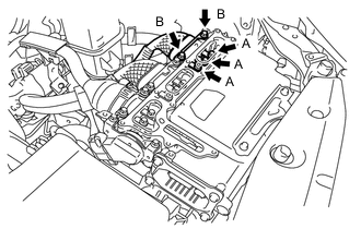
Check that the bolts for the motor cable are tightened to the specified torque, the motor cable is connected securely, and there are no contact problems.
Specified Condition Bolt A T = 8.0 N*m (82 kgf*cm, 71 in.*lbf) Bolt B T = 9.2 N*m (94 kgf*cm, 81 in.*lbf) Note
-
Make sure that the tightening torque of the bolt A is between 6.4 and 9.6 N*m (65 and 98 kgf*cm, 57 and 85 in.*lbf).
-
Make sure that the tightening torque of the bolt B is between 6.4 and 12 N*m (65 and 122 kgf*cm, 57 and 106 in.*lbf).
-
-
Disconnect the motor cable from the inverter with converter assembly.
-
Check for arc marks at the terminals for the motor cable.
Result Result Proceed to The terminals are connected securely and there are no contact problems. There are no arc marks. A The terminals are not connected securely and there is a contact problem. There are arc marks. B The terminals are not connected securely and there is a contact problem. There are no arc marks. C The terminals are connected securely and there are no contact problems. There are arc marks. B -
Connect the motor cable to the inverter with converter assembly.
-
Install the inverter cover.
B
REPLACE MALFUNCTIONING PARTS
C
CONNECT SECURELY
A
-
-
CHECK HYBRID VEHICLE TRANSAXLE ASSEMBLY (MG1)
Result Proceed to OK NG CAUTION:
Be sure to wear insulated gloves.
-
Check that the service plug grip is not installed.
Note
After removing the service plug grip, do not turn the power switch on (READY), unless instructed by the repair manual because this may cause a malfunction.
-
Remove the inverter cover from the inverter with converter assembly.
-
Disconnect the generator cable and motor cable from the inverter with converter assembly.
-
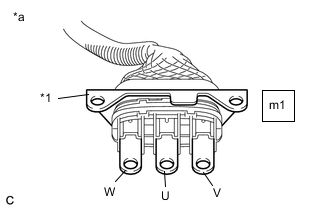
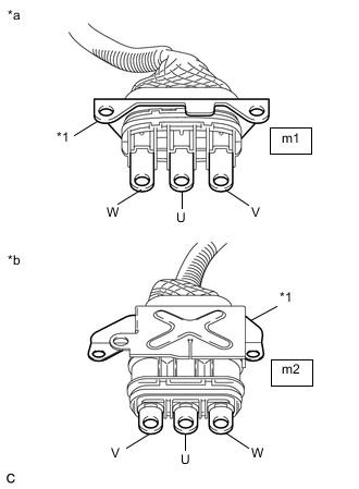
*1 Shield Ground *a Generator Cable
(Inverter with Converter Assembly Side)
Check MG1 for an interphase short using a milliohmmeter.
-
Using a milliohmmeter, measure the resistance according to the value(s) in the table below.
Tech Tips
If the MG1 temperature is high, the resistance will vary greatly from the specification. Therefore, measure the resistance at least 8 hours after the vehicle is stopped.
Standard Resistance Tester Connection Condition Specified Condition m1-1 (W) -m1-3 (V) Power switch off 89.5 to 98.9 mΩ m1-2 (U) - m1-1 (W) Power switch off 89.5 to 98.9 mΩ m1-3 (V) - m1-2 (U) Power switch off 89.5 to 98.9 mΩ Tech Tips
To correct the variation of the measured resistance due to temperature, use the following formula to calculate the resistance at 20°C (68° F).
R20 = Rt / {1 + 0.00393 X (T - 20)}
The calculation is based on the following:
R20: Resistance at 20°C (68° F) (mΩ)
Rt: Measured resistance (mΩ)
T: Temperature when the resistance is measured (°C)
-
-
Using a megohmmeter set to 500 V, measure the resistance according to the value(s) in the table below.
Note
Be sure to set the megohmmeter to 500 V when performing this test. Using a setting higher than 500 V can result in damage to the component being inspected.
Standard Resistance Tester Connection Condition Specified Condition m1-1 (W) - Body ground and shield ground Power switch off 100 MΩ or higher m1-2 (U) - Body ground and shield ground Power switch off 100 MΩ or higher m1-3 (V) - Body ground and shield ground Power switch off 100 MΩ or higher -
Connect the generator cable and motor cable.
-
Install the inverter cover.
Result Proceed to OK NG
NG
CHECK HYBRID VEHICLE TRANSAXLE ASSEMBLY (GENERATOR CABLE CONNECTION CONDITION) Click here
OK
-
-
CHECK HYBRID VEHICLE TRANSAXLE ASSEMBLY (MG2)
Result Proceed to OK NG CAUTION:
Be sure to wear insulated gloves.
-
Check that the service plug grip is not installed.
Note
After removing the service plug grip, do not turn the power switch on (READY), unless instructed by the repair manual because this may cause a malfunction.
-
Remove the inverter cover from the inverter with converter assembly.
-
Disconnect the generator cable and motor cable from the inverter with converter assembly.
-
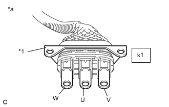
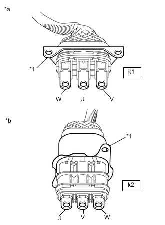
*1 Shield Ground *a Motor Cable
(Inverter with Converter Assembly Side)
Check MG2 for an interphase short using a milliohmmeter.
-
Using a milliohmmeter, measure the resistance according to the value(s) in the table below.
Tech Tips
If the MG2 temperature is high, the resistance will vary greatly from the specification. Therefore, measure the resistance at least 8 hours after the vehicle is stopped.
Standard Resistance Tester Connection Condition Specified Condition k1-1 (W) - k1-3 (V) Power switch off 151.6 to 168.0 mΩ k1-2 (U) - k1-1 (W) Power switch off 152.6 to 169.0 mΩ k1-3 (V) - k1-2 (U) Power switch off 157.6 to 174.0 mΩ Tech Tips
To correct the variation of the measured resistance due to temperature, use the following formula to calculate the resistance at 20°C (68° F).
R20 = Rt / {1 + 0.00393 X (T - 20)}
The calculation is based on the following:
R20: Resistance at 20°C (68° F) (mΩ)
Rt: Measured resistance (mΩ)
T: Temperature when the resistance is measured (°C)
-
-
Using a megohmmeter set to 500 V, measure the resistance according to the value(s) in the table below.
Note
Be sure to set the megohmmeter to 500 V when performing this test. Using a setting higher than 500 V can result in damage to the component being inspected.
Standard Resistance Tester Connection Condition Specified Condition k1-1 (W) - Body ground and shield ground Power switch off 100 MΩ or higher k1-2 (U) - Body ground and shield ground Power switch off 100 MΩ or higher k1-3 (V) - Body ground and shield ground Power switch off 100 MΩ or higher -
Connect the generator cable and motor cable.
-
Install the inverter cover.
Result Proceed to OK NG
NG
CHECK HYBRID VEHICLE TRANSAXLE ASSEMBLY (MOTOR CABLE CONNECTION CONDITION) Click here
OK
-
-
CHECK FUSE (PCU)
Result Proceed to OK NG
-
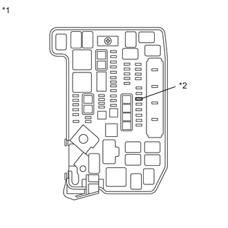
*1 No. 1 Engine Room Relay Block and No. 1 Junction Block Assembly *2 PCU Fuse Remove the PCU fuse from the No. 1 engine room relay block and No. 1 junction block assembly.
-
Measure the resistance according to the value(s) in the table below.
Standard Resistance Tester Connection Condition Specified Condition PCU fuse terminal Always Below 1 Ω -
Install the PCU fuse.
Result Proceed to OK NG
NG
CHECK HARNESS AND CONNECTOR (INVERTER WITH CONVERTER ASSEMBLY - PCU FUSE) Click here
OK
-
-
CHECK HARNESS AND CONNECTOR (INVERTER WITH CONVERTER ASSEMBLY POWER SOURCE CIRCUIT)
Result Proceed to OK NG CAUTION:
Be sure to wear insulated gloves.
-
Check that the service plug grip is not installed.
Note
After removing the service plug grip, do not turn the power switch on (READY), unless instructed by the repair manual because this may cause a malfunction.
-
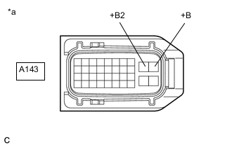
Disconnect the A143 inverter with converter assembly connector.
-
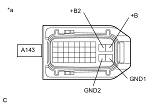
*a Front view of wire harness connector
(to Inverter with Converter Assembly)
Measure the resistance according to the value(s) in the table below.
Standard Resistance Tester Connection Condition Specified Condition A143-28 (GND1) - Body ground Power switch off Below 1 Ω A143-27 (GND2) - Body ground Power switch off Below 1 Ω -
Connect the cable to the negative (-) auxiliary battery terminal.
-
Turn the power switch on (IG).
-
Measure the voltage according to the value(s) in the table below.
Standard Voltage Tester Connection Condition Specified Condition A143-10 (+B) - Body ground Power switch on (IG) 11 to 14 V A143-9 (+B2) - Body ground Power switch on (IG) 11 to 14 V Note
Turning the power switch on (IG) with the inverter with converter assembly connector disconnected causes other DTCs to be stored. Clear the DTCs after performing this inspection.
-
Turn the power switch off.
-
Disconnect the cable from the negative (-) auxiliary battery terminal.
-
Reconnect the A143 inverter with converter assembly connector.
Result Proceed to OK NG
NG
REPAIR OR REPLACE POWER SOURCE CIRCUIT
OK
-
-
CHECK HARNESS AND CONNECTOR (HYBRID VEHICLE CONTROL ECU ASSEMBLY - INVERTER WITH CONVERTER ASSEMBLY)
Result Proceed to OK NG CAUTION:
Be sure to wear insulated gloves.
-
Check that the service plug grip is not installed.
Note
After removing the service plug grip, do not turn the power switch on (READY), unless instructed by the repair manual because this may cause a malfunction.
-
Disconnect the A150 hybrid vehicle control ECU assembly connector.
-
Disconnect the A143 inverter with converter assembly connector.
-
Measure the resistance according to the value(s) in the table below.
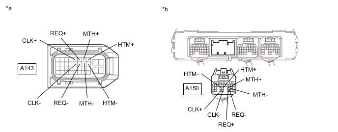
*a Front view of wire harness connector
(to Inverter with Converter Assembly)
*b Rear view of wire harness connector
(to Hybrid Vehicle Control ECU Assembly)
Standard Resistance (Check for Open) Tester Connection Condition Specified Condition A143-8 (HTM+) - A150-24 (HTM+) Power switch off Below 1 Ω A143-18 (HTM-) - A150-25 (HTM-) Power switch off Below 1 Ω A143-7 (MTH+) - A150-23 (MTH+) Power switch off Below 1 Ω A143-17 (MTH-) - A150-22 (MTH-) Power switch off Below 1 Ω A143-6 (REQ+) - A150-31 (REQ+) Power switch off Below 1 Ω A143-16 (REQ-) - A150-30 (REQ-) Power switch off Below 1 Ω A143-5 (CLK+) - A150-33 (CLK+) Power switch off Below 1 Ω A143-15 (CLK-) - A150-32 (CLK-) Power switch off Below 1 Ω Standard Resistance (Check for Short) Tester Connection Condition Specified Condition A143-8 (HTM+) or A150-24 (HTM+) - Body ground and other terminals Power switch off 10 kΩ or higher A143-18 (HTM-) or A150-25 (HTM-) - Body ground and other terminals Power switch off 10 kΩ or higher A143-7 (MTH+) or A150-23 (MTH+) - Body ground and other terminals Power switch off 10 kΩ or higher A143-17 (MTH-) or A150-22 (MTH-) - Body ground and other terminals Power switch off 10 kΩ or higher A143-6 (REQ+) or A150-31 (REQ+) - Body ground and other terminals Power switch off 10 kΩ or higher A143-16 (REQ-) or A150-30 (REQ-) - Body ground and other terminals Power switch off 10 kΩ or higher A143-5 (CLK+) or A150-33 (CLK+) - Body ground and other terminals Power switch off 10 kΩ or higher A143-15 (CLK-) or A150-32 (CLK-) - Body ground and other terminals Power switch off 10 kΩ or higher -
Connect the cable to the negative (-) auxiliary battery terminal.
-
Turn the power switch on (IG).
-
Measure the voltage according to the value(s) in the table below.
Standard Voltage Tester Connection Condition Specified Condition A143-8 (HTM+) or A150-24 (HTM+) - Body ground Power switch on (IG) Below 1 V A143-18 (HTM-) or A150-25 (HTM-) - Body ground Power switch on (IG) Below 1 V A143-7 (MTH+) or A150-23 (MTH+) - Body ground Power switch on (IG) Below 1 V A143-17 (MTH-) or A150-22 (MTH-) - Body ground Power switch on (IG) Below 1 V A143-6 (REQ+) or A150-31 (REQ+) - Body ground Power switch on (IG) Below 1 V A143-16 (REQ-) or A150-30 (REQ-) - Body ground Power switch on (IG) Below 1 V A143-5 (CLK+) or A150-33 (CLK+) - Body ground Power switch on (IG) Below 1 V A143-15 (CLK-) or A150-32 (CLK-) - Body ground Power switch on (IG) Below 1 V Note
Turning the power switch on (IG) with the hybrid vehicle control ECU assembly and inverter with converter assembly connectors disconnected causes other DTCs to be stored. Clear the DTCs after performing this inspection.
-
Turn the power switch off.
-
Disconnect the cable from the negative (-) auxiliary battery terminal.
-
Reconnect the A143 inverter with converter assembly connector.
-
Reconnect the A150 hybrid vehicle control ECU assembly connector.
Result Proceed to OK NG
NG
REPAIR OR REPLACE HARNESS OR CONNECTOR
OK
-
-
CHECK HYBRID VEHICLE CONTROL ECU ASSEMBLY
Result Proceed to OK NG
-
Disconnect the A150 hybrid vehicle control ECU assembly connector.
-
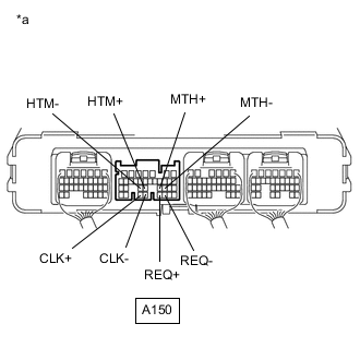
*a Component without harness connected
(Hybrid Vehicle Control ECU Assembly)
Measure the resistance according to the value(s) in the table below.
Standard Resistance Tester Connection Condition Specified Condition A150-24 (HTM+) - A150-25 (HTM-) Power switch off 80 to 170 Ω A150-23 (MTH+) - A150-22 (MTH-) Power switch off 80 to 170 Ω A150-31 (REQ+) - A150-30 (REQ-) Power switch off 80 to 170 Ω A150-33 (CLK+) - A150-32 (CLK-) Power switch off 80 to 170 Ω -
Reconnect the A150 hybrid vehicle control ECU assembly connector.
Result Proceed to OK NG
NG
REPLACE HYBRID VEHICLE CONTROL ECU ASSEMBLY for LHD: Click here
REPLACE HYBRID VEHICLE CONTROL ECU ASSEMBLY for RHD: Click hereOK
-
-
CHECK CONNECTOR CONNECTION CONDITION (GENERATOR RESOLVER CONNECTOR)
Result Proceed to OK NG
-
Check the connection of the generator resolver connector.
OK The connector is connected securely and there are no contact problems. Result Proceed to OK NG
NG
CONNECT SECURELY
OK
-
-
CHECK CONNECTOR CONNECTION CONDITION (MOTOR RESOLVER CONNECTOR)
Result Proceed to OK NG
-
Check the connection of the motor resolver connector.
OK The connector is connected securely and there are no contact problems. Result Proceed to OK NG
OK
REFER TO REPLACE INVERTER WITH CONVERTER ASSEMBLY PARTS Click here
NG
CONNECT SECURELY
-
-
REPLACE HV COOLANT
Result Proceed to NEXT
-
Replace the HV coolant with coolant having an appropriate concentration (appropriate freeze point) for the vehicle usage conditions.
Result Proceed to NEXT
NEXT
COMPLETED
-
-
CHECK CONNECTOR CONNECTION CONDITION (GENERATOR RESOLVER CONNECTOR)
Result Proceed to OK NG
-
Check the connection of the generator resolver connector.
OK The connector is connected securely and there are no contact problems. Result Proceed to OK NG
NG
CONNECT SECURELY
OK
-
-
INSPECT HYBRID VEHICLE TRANSAXLE ASSEMBLY (GENERATOR RESOLVER)
Result Proceed to OK NG
-
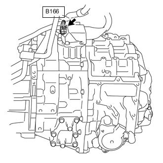
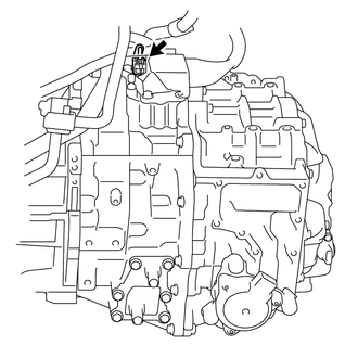
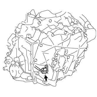
Disconnect the B166 generator resolver connector.
-
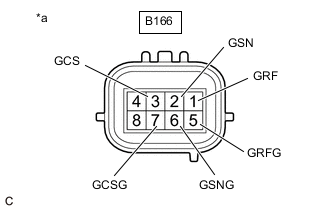
*a Component without harness connected
(Generator Resolver (Hybrid Vehicle Transaxle Assembly))
Measure the resistance according to the value(s) in the table below.
Standard Resistance Tester Connection Condition Specified Condition B166-1 (GRF) - B166-5 (GRFG) Power switch off 7.1 to 21.6 Ω B166-2 (GSN) - B166-6 (GSNG) Power switch off 13.7 to 34.5 Ω B166-3 (GCS) - B166-7 (GCSG) Power switch off 12.8 to 32.4 Ω Standard Resistance (Check for Short) Tester Connection Condition Specified Condition B166-1 (GRF) - Body ground and other terminals Power switch off 1 MΩ or higher B166-5 (GRFG) - Body ground and other terminals Power switch off 1 MΩ or higher B166-2 (GSN) - Body ground and other terminals Power switch off 1 MΩ or higher B166-6 (GSNG) - Body ground and other terminals Power switch off 1 MΩ or higher B166-3 (GCS) - Body ground and other terminals Power switch off 1 MΩ or higher B166-7 (GCSG) - Body ground and other terminals Power switch off 1 MΩ or higher Tech Tips
The generator resolver is not available as a supply part. If it requires replacement, replace the hybrid vehicle transaxle assembly.
-
Reconnect the B166 generator resolver connector.
Result Proceed to OK NG
OK
REPAIR OR REPLACE HARNESS OR CONNECTOR
NG
REPLACE HYBRID VEHICLE GENERATOR ASSEMBLY Click here
-
-
CHECK CONNECTOR CONNECTION CONDITION (MOTOR RESOLVER CONNECTOR)
Result Proceed to OK NG
-
Check the connection of the motor resolver connector.
OK The connector is connected securely and there are no contact problems. Result Proceed to OK NG
NG
CONNECT SECURELY
OK
-
-
INSPECT HYBRID VEHICLE TRANSAXLE ASSEMBLY (MOTOR RESOLVER)
Result Proceed to OK NG
-
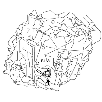
Disconnect the B168 motor resolver connector.
-
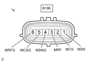
*a Component without harness connected
(Motor Resolver (Hybrid Vehicle Transaxle Assembly))
Measure the resistance according to the value(s) in the table below.
Standard Resistance (Check for Open) Tester Connection Condition Specified Condition B168-3 (MRF) - B168-6 (MRFG) Power switch off 7.1 to 21.6 Ω B168-1 (MSN) - B168-4 (MSNG) Power switch off 13.7 to 34.5 Ω B168-2 (MCS) - B168-5 (MCSG) Power switch off 12.8 to 32.4 Ω Standard Resistance (Check for Short) Tester Connection Condition Specified Condition B168-3 (MRF) - Body ground and other terminals Power switch off 1 MΩ or higher B168-6 (MRFG) - Body ground and other terminals Power switch off 1 MΩ or higher B168-1 (MSN) - Body ground and other terminals Power switch off 1 MΩ or higher B168-4 (MSNG) - Body ground and other terminals Power switch off 1 MΩ or higher B168-2 (MCS) - Body ground and other terminals Power switch off 1 MΩ or higher B168-5 (MCSG) - Body ground and other terminals Power switch off 1 MΩ or higher Tech Tips
The motor resolver is not available as a supply part. If it requires replacement, replace the hybrid vehicle transaxle assembly.
-
Reconnect the B168 motor resolver connector.
Result Proceed to OK NG
OK
REPAIR OR REPLACE HARNESS OR CONNECTOR
NG
REPLACE HYBRID VEHICLE MOTOR ASSEMBLY Click here
-
-
CHECK HYBRID VEHICLE TRANSAXLE ASSEMBLY (GENERATOR CABLE CONNECTION CONDITION)
Result Proceed to A B C CAUTION:
Be sure to wear insulated gloves.
-
Check that the service plug grip is not installed.
Note
After removing the service plug grip, do not turn the power switch on (READY), unless instructed by the repair manual because this may cause a malfunction.
-
Remove the inverter with converter assembly.
-
Check that the bolts for the generator cable are tightened to the specified torque, the generator cable is connected securely, and there are no contact problems.
Specified Condition Bolt A T = 20 N*m (204 kgf*cm, 15 ft.*lbf) Bolt B T = 10 N*m (102 kgf*cm, 7 ft.*lbf) Note
-
Make sure that the tightening torque of the bolt A is between 16 and 24 N*m (163 to 245 kgf*cm, 12 to 18 ft.*lbf).
-
Make sure that the tightening torque of the bolt B is between 8 and 12 N*m (82 and 122 kgf*cm, 71 and 106 in.*lbf).
-
-
Disconnect the generator cable from the hybrid vehicle transaxle assembly.
-
Check for arc marks at the terminals for the generator cable.
Result Result Proceed to The terminals are connected securely and there are no contact problems. There are no arc marks. A The terminals are not connected securely and there is a contact problem. There are arc marks. B The terminals are not connected securely and there is a contact problem. There are no arc marks. C The terminals are connected securely and there are no contact problems. There are arc marks. B -
Connect the generator cable to the hybrid vehicle transaxle assembly.
-
Install the inverter with converter assembly.
B
REPLACE MALFUNCTIONING PARTS
C
CONNECT SECURELY
A
-
-
CHECK GENERATOR CABLE
Result Proceed to OK NG CAUTION:
Be sure to wear insulated gloves.
-
Check that the service plug grip is not installed.
Note
After removing the service plug grip, do not turn the power switch on (READY), unless instructed by the repair manual because this may cause a malfunction.
-
Remove the generator cable.
-
*1 Shield ground *a Generator Cable
(Inverter with Converter Assembly Side)
*b Generator Cable
(Hybrid Vehicle Transaxle Assembly Side)
Using a megohmmeter set to 500 V, measure the resistance according to the value(s) in the table below.
Note
Be sure to set the megohmmeter to 500 V when performing this test. Using a setting higher than 500 V can result in damage to the component being inspected.
Standard Resistance Tester Connection Condition Specified Condition m1-1 (W) - Body ground and shield ground Power switch off 100 MΩ or higher m1-2 (U) - Body ground and shield ground Power switch off 100 MΩ or higher m1-3 (V) - Body ground and shield ground Power switch off 100 MΩ or higher Note
Wrap the terminal of the generator cable with insulating tape to prevent them from coming into contact with body ground.
-
Measure the resistance according to the value(s) in the table below.
Standard Resistance Tester Connection Condition Specified Condition m1-1 (W) - m2-2 (U) Power switch off 100 MΩ or higher m1-2 (U) - m2-1 (V) Power switch off 100 MΩ or higher m1-3 (V) - m2-3 (W) Power switch off 100 MΩ or higher m1-1 (W) - m2-3 (W) Power switch off Below 1 Ω m1-2 (U) - m2-2 (U) Power switch off Below 1 Ω m1-3 (V) - m2-1 (V) Power switch off Below 1 Ω -
Install the generator cable.
Result Proceed to OK NG
OK
REPLACE HYBRID VEHICLE GENERATOR ASSEMBLY Click here
NG
REPLACE GENERATOR CABLE Click here
-
-
CHECK HYBRID VEHICLE TRANSAXLE ASSEMBLY (MOTOR CABLE CONNECTION CONDITION)
Result Proceed to A B C CAUTION:
Be sure to wear insulated gloves.
-
Check that the service plug grip is not installed.
Note
After removing the service plug grip, do not turn the power switch on (READY), unless instructed by the repair manual because this may cause a malfunction.
-
Check that the bolts for the motor cable are tightened to the specified torque, the motor cable is connected securely, and there are no contact problems.
Specified Condition T = 10 N*m (102 kgf*cm, 7 ft.*lbf) Note
Make sure that the tightening torque of the bolt is between 8 and 12 N*m (82 and 122 kgf*cm, 71 and 106 in.*lbf).
-
Disconnect the motor cable from the hybrid vehicle transaxle assembly.
-
Check for arc marks at the terminals for the motor cable.
Result Result Proceed to The terminals are connected securely and there are no contact problems. There are no arc marks. A The terminals are not connected securely and there is a contact problem. There are arc marks. B The terminals are not connected securely and there is a contact problem. There are no arc marks. C The terminals are connected securely and there are no contact problems. There are arc marks. B -
Connect the motor cable to the hybrid vehicle transaxle assembly.
B
REPLACE MALFUNCTIONING PARTS
C
CONNECT SECURELY
A
-
-
CHECK MOTOR CABLE
Result Proceed to OK NG CAUTION:
Be sure to wear insulated gloves.
-
Check that the service plug grip is not installed.
Note
After removing the service plug grip, do not turn the power switch on (READY), unless instructed by the repair manual because this may cause a malfunction.
-
Remove the motor cable.
-
*1 Shield ground *a Motor Cable
(Inverter with Converter Assembly Side)
*b Motor Cable
(Hybrid Vehicle Transaxle Assembly Side)
Using a megohmmeter set to 500 V, measure the resistance according to the value(s) in the table below.
Note
Be sure to set the megohmmeter to 500 V when performing this test. Using a setting higher than 500 V can result in damage to the component being inspected.
Standard Resistance Tester Connection Condition Specified Condition k1-1 (W) - Body ground and shield ground Power switch off 100 MΩ or higher k1-2 (U) - Body ground and shield ground Power switch off 100 MΩ or higher k1-3 (V) - Body ground and shield ground Power switch off 100 MΩ or higher Note
Wrap the terminal of the motor cable with insulating tape to prevent them from coming into contact with body ground.
-
Measure the resistance according to the value(s) in the table below.
Standard Resistance Tester Connection Condition Specified Condition k1-1 (W) - k2-3 (U) Power switch off 100 MΩ or higher k1-2 (U) - k2-2 (V) Power switch off 100 MΩ or higher k1-3 (V) - k2-1 (W) Power switch off 100 MΩ or higher k1-1 (W) - k2-1 (W) Power switch off Below 1 Ω k1-2 (U) - k2-3 (U) Power switch off Below 1 Ω k1-3 (V) - k2-2 (V) Power switch off Below 1 Ω -
Install the motor cable.
Result Proceed to OK NG
OK
REPLACE HYBRID VEHICLE MOTOR ASSEMBLY Click here
NG
REPLACE MOTOR CABLE Click here
-
-
CHECK HARNESS AND CONNECTOR (INVERTER WITH CONVERTER ASSEMBLY - PCU FUSE)
Result Proceed to OK NG CAUTION:
Be sure to wear insulated gloves.
-
Check that the service plug grip is not installed.
Note
After removing the service plug grip, do not turn the power switch on (READY), unless instructed by the repair manual because this may cause a malfunction.
-
Disconnect the A143 inverter with converter assembly connector.
-
*a Front view of wire harness connector
(to Inverter with Converter Assembly)
Measure the resistance according to the value(s) in the table below.
Standard Resistance Tester Connection Condition Specified Condition A143-10 (+B) - Body ground Power switch off 10 kΩ or higher A143-9 (+B2) - Body ground Power switch off 10 kΩ or higher -
Reconnect the A143 inverter with converter assembly connector.
Result Proceed to OK NG
NG
REPAIR OR REPLACE HARNESS OR CONNECTOR Click here
OK
-
-
REFER TO REPLACE INVERTER WITH CONVERTER ASSEMBLY PARTS
Result Proceed to NEXT
NEXT
REPLACE FUSE (PCU)
-
REPAIR OR REPLACE HARNESS OR CONNECTOR
Result Proceed to NEXT
NEXT
REPLACE FUSE (PCU)