HYBRID CONTROL SYSTEM, Diagnostic DTC:P0A08-264
| DTC Code | DTC Name |
|---|---|
| P0A08-264 | DC / DC Converter Status Circuit |
DESCRIPTION
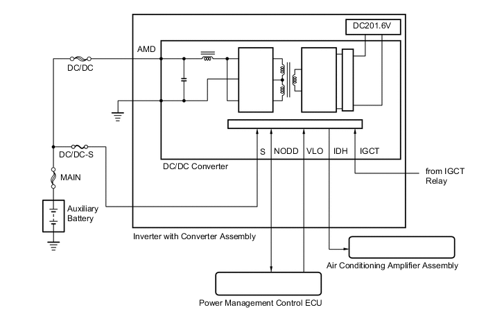
The DC/DC converter converts the DC 201.6 V of the HV battery into DC 12 V in order to supply power to areas such as the vehicle's lighting, audio, and ECU systems. In addition, it charges the auxiliary battery. A transistor bridge circuit initially converts DC 201.6 V into alternating current, and a transformer lowers its voltage. Then, it is rectified and smoothed (into DC) and converted into DC 12 V. The DC/DC converter controls the output voltage in order to keep a constant voltage at the terminals of the auxiliary battery.
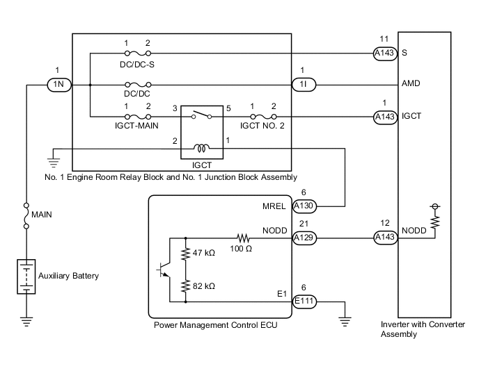
The power management control ECU uses the NODD signal line to transmit a stop command to the DC/DC converter and receive signals indicating the normal or abnormal condition of the 12 V charging system. If the vehicle is being driven with an inoperative DC/DC converter, the voltage of the auxiliary battery will drop, which will prevent the continued operation of the vehicle. Therefore, the power management control ECU monitors the operation of the DC/DC converter and alerts the driver if it detects a malfunction.
| DTC No. | Detection Item | DTC Detection Condition | Trouble Area | MIL | Warning Indicate |
|---|---|---|---|---|---|
| P0A08-264 | DC / DC Converter Status Circuit | DC/DC converter malfunction or the auxiliary battery voltage drops to 11 V or less with the power switch on (READY). |
|
Does not come on | Master Warning Light: Comes on |
CAUTION / NOTICE / HINT
CAUTION:
-
Before inspecting the high-voltage system or disconnecting the low voltage connector of the inverter with converter assembly, take safety precautions such as wearing insulated gloves and removing the service plug grip to prevent electrical shocks. After removing the service plug grip, put it in your pocket to prevent other technicians from accidentally reconnecting it while you are working on the high-voltage system.
-
After removing the service plug grip, wait for at least 10 minutes before touching any of the high-voltage connectors or terminals. After waiting for 10 minutes, check the voltage at the terminals in the inspection point in the inverter with converter assembly. The voltage should be 0 V before beginning work.
Tech Tips
Waiting for at least 10 minutes is required to discharge the high-voltage capacitor inside the inverter with converter assembly.
Note
After turning the power switch off, waiting time may be required before disconnecting the cable from the negative (-) auxiliary battery terminal. Therefore, make sure to read the disconnecting the cable from the negative (-) auxiliary battery terminal notices before proceeding with work.
Tech Tips
-
If the DC/DC converter is malfunctioning, the auxiliary battery cannot be charged. Therefore, once the power switch is turned off, it may be impossible to turn it on (READY) again if the auxiliary battery is completely discharged. In this case, charge the auxiliary battery. Be careful as charging is not performed during the inspection.
-
If the power switch turns off immediately after it is turned on (READY), the auxiliary battery voltage may be low. Charge the auxiliary battery.
PROCEDURE
-
CHECK DTC OUTPUT (HYBRID CONTROL)
-
Connect the GTS to the DLC3.
-
Turn the power switch on (IG).
-
Enter the following menus: Powertrain / Hybrid Control / Trouble Codes.
-
Check for DTCs.
Powertrain > Hybrid Control > Trouble CodesResult Result Proceed to P0A08-264 only is output, or DTCs except the ones in the table below are also output. A Any of the following DTCs including pending DTCs are also output. B DTC No. Relevant Diagnosis P0A93-346 Inverter Cooling System Performance P0A94-547, 548, 549 DC / DC Converter Performance P0AA6-526, 613 Hybrid Battery Voltage System Isolation Fault P0ADB-227 Hybrid Battery Positive Contactor Control Circuit Low P0ADF-229 Hybrid Battery Negative Contactor Control Circuit Low P0AE6-225 Hybrid Battery Precharge Contactor Control Circuit Low P0C73-776 Motor Electronics Coolant Pump "A" Control Performance P3004-131, 803 High Voltage Power Resource P314A-828 Inverter Coolant Pump Speed Signal -
Turn the power switch off.
B 
GO TO DTC CHART (HYBRID CONTROL SYSTEM) Click here
A 
-
-
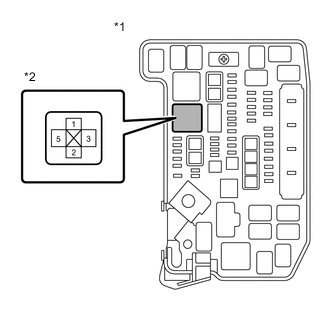
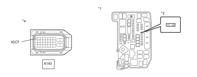
CHECK FUSE (IGCT NO. 2)
-
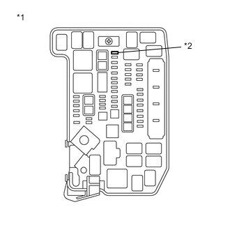
Remove the IGCT NO. 2 fuse from the No. 1 engine room relay block and No. 1 junction block assembly.
-
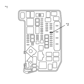
*1 No. 1 Engine Room Relay Block and No. 1 Junction Block Assembly *2 IGCT NO. 2 Fuse Measure the resistance according to the value(s) in the table below.
Standard Resistance Tester Connection Condition Specified Condition IGCT NO. 2 fuse terminals Always Below 1 Ω -
Install the IGCT NO. 2 fuse.
Result Proceed to OK NG
NG 
CHECK HARNESS AND CONNECTOR (INVERTER WITH CONVERTER ASSEMBLY - IGCT NO. 2 FUSE) Click here
OK
-
-
CHECK FUSE (DC/DC-S)
-
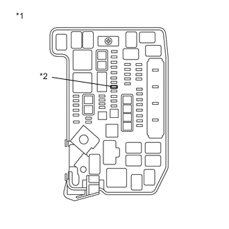
*1 No. 1 Engine Room Relay Block and No. 1 Junction Block Assembly *2 DC/DC-S Fuse Remove the DC/DC-S fuse from the No. 1 engine room relay block and No. 1 junction block assembly.
-
Measure the resistance according to the value(s) in the table below.
Standard Resistance Tester Connection Condition Specified Condition DC/DC-S fuse terminals Always Below 1 Ω -
Install the DC/DC-S fuse.
Result Proceed to OK NG
NG
CHECK HARNESS AND CONNECTOR (INVERTER WITH CONVERTER ASSEMBLY - DC/DC-S FUSE) Click here
OK
-
-
CHECK FUSE (IGCT-MAIN)
-
*1 No. 1 Engine Room Relay Block and No. 1 Junction Block Assembly *2 IGCT-MAIN Fuse Remove the IGCT-MAIN fuse from the No. 1 engine room relay block and No. 1 junction block assembly.
-
Measure the resistance according to the value(s) in the table below.
Standard Resistance Tester Connection Condition Specified Condition IGCT-MAIN fuse terminals Always Below 1 Ω -
Install the IGCT-MAIN fuse.
Result Proceed to OK NG
NG
CHECK NO. 1 ENGINE ROOM RELAY BLOCK AND NO. 1 JUNCTION BLOCK ASSEMBLY (IGCT RELAY, IGCT FUSE, IGCT NO. 2 FUSE) Click here
OK
-
-
CHECK FUSIBLE LINK (DC/DC)
-
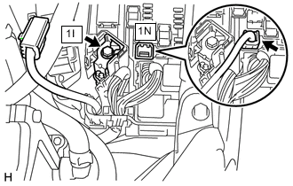
Disconnect the 1N No. 1 engine room relay block and No. 1 junction block assembly connector.
-
Measure the resistance according to the value(s) in the table below.
Standard Resistance Tester Connection Condition Specified Condition 1I-1 (AMD) - 1N-1 Always Below 1 Ω -
Check the fusible links (DC/DC) in the No. 1 engine room relay block and No. 1 junction block assembly for improper installation.
OK The fusible link is installed securely. -
Reconnect the 1N No. 1 engine room relay block and No. 1 junction block assembly connector.
Result Proceed to OK NG
NG
REPLACE FUSIBLE LINK (DC/DC)
OK
-
-
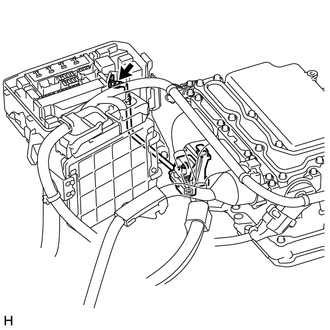
CHECK CONNECTOR CONNECTION CONDITION (POWER MANAGEMENT CONTROL ECU CONNECTOR)
Result Proceed to OK NG
-
Check the connector connections and contact pressure of the relevant terminals for the power management control ECU connectors.
OK The connectors are connected securely and there are no contact pressure problems. 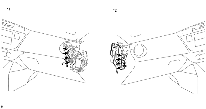
*1 for LHD *2 for RHD Result Proceed to OK NG
NG
CONNECT SECURELY
OK
-
-
CHECK CONNECTOR CONNECTION CONDITION (INVERTER WITH CONVERTER ASSEMBLY CONNECTOR)
Result Proceed to OK NG CAUTION:
Be sure to wear insulated gloves.
-
Check that the service plug grip is not installed.
Note
After removing the service plug grip, do not turn the power switch on (READY), unless instructed by the repair manual because this may cause a malfunction.
-
Check the connector connections and contact pressure of the low voltage connectors of the inverter with converter assembly.
Note
Before disconnecting the connector, confirm that it is properly connected by checking that the locking claws are engaged and that the connector does not pull out.
OK The connectors are connected securely and there are no contact pressure problems. Tech Tips
When connecting the connector, insert it with the locking lever in the raised position. Rotate the lever downward and make sure that the connector is pulled into its socket. When the locking lever is in its fully closed position, a click will be heard as its locking claws engage. After the click is heard, pull up on the connector to confirm that it is properly connected.
Result Proceed to OK NG
NG
CONNECT SECURELY
OK
-
-
CHECK CABLE AND WIRE HARNESS
CAUTION:
Be sure to wear insulated gloves.
-
Check that the service plug grip is not installed.
Note
After removing the service plug grip, do not turn the power switch on (READY), unless instructed by the repair manual because this may cause a malfunction.
-
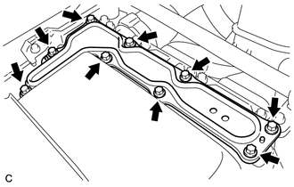
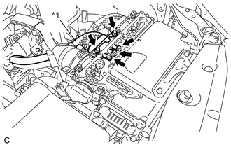
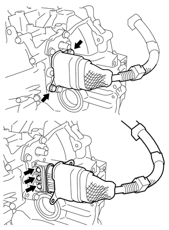
Remove the inverter cover from the inverter with converter assembly.
-
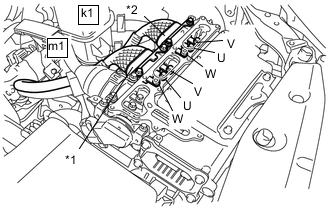
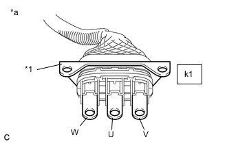
*1 Generator Cable *2 Motor Cable Using a megohmmeter set to 500 V, measure the insulation resistance according to the value(s) in the table below.
Note
Be sure to set the megohmmeter to 500 V when performing this test. Using a setting higher than 500 V can result in damage to the component being inspected.
Standard Resistance Tester Connection Condition Specified Condition m1-1 (W) - Body ground and shield ground Power switch off 1 MΩ or higher m1-2 (U) - Body ground and shield ground Power switch off 1 MΩ or higher m1-3 (V) - Body ground and shield ground Power switch off 1 MΩ or higher k1-1 (W) - Body ground and shield ground Power switch off 1 MΩ or higher k1-2 (U) - Body ground and shield ground Power switch off 1 MΩ or higher k1-3 (V) - Body ground and shield ground Power switch off 1 MΩ or higher Tech Tips
Perform this inspection while the generator cable and motor cable are connected.
-
Install the inverter cover to the inverter with converter assembly.
Result Proceed to OK NG
NG
CHECK HYBRID VEHICLE TRANSAXLE ASSEMBLY (MG1) Click here
OK
-
-
CHECK AMD TERMINAL CONNECTION CONDITION
CAUTION:
Be sure to wear insulated gloves.
-
Check that the service plug grip is not installed.
Note
After removing the service plug grip, do not turn the power switch on (READY), unless instructed by the repair manual because this may cause a malfunction.
-
Check that the bolts for the AMD terminal are tightened to the specified torque, the AMD terminal is connected securely, and there is no contact problem.
Torque T = 8.0 N*m {82 kgf*cm, 71in.*lbf } Result Result Proceed to There are no arc marks. The terminal is connected securely and there is no contact problem. A There are no arc marks. The terminal is not connected securely and there is a contact problem. B There are arc marks. - C
B
CONNECT SECURELY
C
REPLACE MALFUNCTIONING PARTS
A
-
-
CHECK AMD TERMINAL VOLTAGE
CAUTION:
Be sure to wear insulated gloves.
-
Connect the cable to the negative (-) auxiliary battery terminal.
-
Measure the voltage according to the value(s) in the table below.
Standard Voltage Tester Connection Condition Specified Condition 1I-1 (AMD) - Body ground Power switch off Same as auxiliary battery voltage -
Disconnect the cable from the negative (-) auxiliary battery terminal.
Result Proceed to OK NG
NG
REPAIR OR REPLACE HARNESS OR CONNECTOR
OK
-
-
CHECK HARNESS AND CONNECTOR (NO. 1 ENGINE ROOM RELAY BLOCK AND NO. 1 JUNCTION BLOCK ASSEMBLY - INVERTER WITH CONVERTER ASSEMBLY)
CAUTION:
Be sure to wear insulated gloves.
-
Check that the service plug grip is not installed.
Note
After removing the service plug grip, do not turn the power switch on (READY), unless instructed by the repair manual because this may cause a malfunction.
-
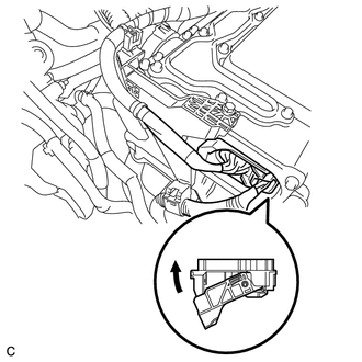
Disconnect the A143 inverter with converter assembly connector.
-
Connect the cable to the negative (-) auxiliary battery terminal.
-
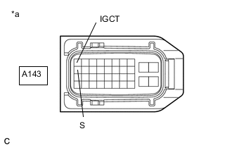
*a Front view of wire harness connector
(to Inverter with Converter Assembly)
Measure the voltage according to the value(s) in the table below.
Standard Voltage Tester Connection Condition Specified Condition A143-11 (S) - Body ground Always Same as auxiliary battery voltage -
Turn the power switch on (IG).
-
Measure the voltage according to the value(s) in the table below.
Standard Voltage Tester Connection Condition Specified Condition A143-1 (IGCT) - Body ground Power switch on (IG) Same as auxiliary battery voltage Note
Turning the power switch on (IG) with the inverter with converter assembly connector disconnected causes other DTCs to be stored. Clear the DTCs after performing this inspection.
-
Turn the power switch off.
-
Disconnect the cable from the negative (-) auxiliary battery terminal.
-
Reconnect the A143 inverter with converter assembly connector.
Result Proceed to OK NG
NG
REPAIR OR REPLACE HARNESS OR CONNECTOR
OK
-
-
CHECK HARNESS AND CONNECTOR (RESISTANCE VALUE OF NODD INSIDE POWER MANAGEMENT CONTROL ECU)
CAUTION:
Be sure to wear insulated gloves.
-
Check that the service plug grip is not installed.
Note
After removing the service plug grip, do not turn the power switch on (READY), unless instructed by the repair manual because this may cause a malfunction.
-
Disconnect the A143 inverter with converter assembly connector.
-
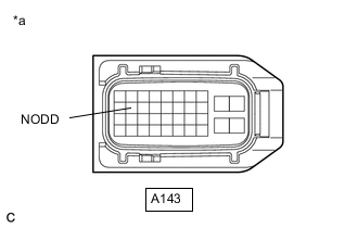
*a Front view of wire harness connector
(to Inverter with Converter Assembly)
Measure the resistance according to the value(s) in the table below.
Standard Resistance Tester Connection Condition Specified Condition A143-12 (NODD) - Body ground Power switch off 110 to 150 kΩ -
Reconnect the A143 inverter with converter assembly connector.
Result Proceed to OK NG
NG
INSPECT POWER MANAGEMENT CONTROL ECU (RESISTANCE VALUE OF NODD INSIDE POWER MANAGEMENT CONTROL ECU) Click here
OK
-
-
CHECK DC/DC CONVERTER FUNCTION
Tech Tips
The current at the AMD terminal cannot be measured directly because of space limitations. Measure the current flowing at the auxiliary battery instead.
-
Connect the AC/DC 400 A probe of the tester to the positive auxiliary battery line.
-
Install the service plug grip.
-
Connect the cable to the negative (-) auxiliary battery terminal.
-
Turn the power switch on (READY) and leave the vehicle as it is until the electric current flowing into the auxiliary battery becomes 10 A or less.
Tech Tips
If the power switch turns off immediately after it is turned on (READY), auxiliary battery voltage may be low. Recharge the auxiliary battery and perform this procedure again.
-
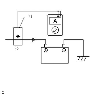
*1 Probe Direction *2 Current Flowing into Auxiliary Battery 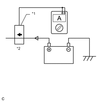
*1 Probe Direction *2 Current Flowing from Auxiliary Battery Measure the current flowing from the auxiliary battery with the power switch on (READY), the headlight position switch and blower motor switch in the HI position, and the rear window defogger turned on.
Standard Current Item Condition Specified Condition Current flowing from auxiliary battery Power switch on (READY)
(The headlight position switch and blower motor switch are in the HI position, and the rear window defogger is turned on.)
0 A or less
(no current from auxiliary battery)
-
Measure the voltage according to the value(s) in the table below.
Standard Voltage Item Condition Specified Condition Auxiliary battery voltage Power switch on (READY)
(The headlight position switch and blower motor switch are in the HI position, and the rear window defogger is turned on.)
13 to 15 V -
Turn the power switch off.
Result Proceed to OK NG
NG
REFER TO REPLACE INVERTER WITH CONVERTER ASSEMBLY PARTS Click here
OK
-
-
CHECK QUANTITY OF HV COOLANT
Result Proceed to A B C
-
Check the HV coolant level in the inverter reserve tank.
-
Check for HV coolant leaks.
Result Result Proceed to No leaks are found and coolant level in the inverter reserve tank assembly is above the low line. A No leaks are found and coolant level in the inverter reserve tank assembly is below the low line. B HV coolant leaks are evident. C Tech Tips
After repairing the HV coolant leaks and adding coolant, perform the "Activate the Water Pump" Active Test (HV Active Test item) and the "Control the Electric Cooling Fan" Active Test (Engine Active Test item) and make sure that there are no malfunctions.
B
ADD HV COOLANT
C
INSPECT FOR HV COOLANT LEAK AND ADD HV COOLANT
A
-
-
CHECK COOLANT HOSE
Result Proceed to OK NG
-
Check if the hoses of the cooling system are kinked or clogged.
Result Proceed to OK NG
NG
CORRECT THE PROBLEM
OK
-
-
PERFORM ACTIVE TEST USING GTS (CONTROL THE ELECTRIC COOLING FAN)
Result Proceed to OK NG
-
Connect the GTS to the DLC3.
-
Turn the power switch on (IG).
-
Enter the following menus: Powertrain / Engine and ECT / Active Test / Control the Electric Cooling Fan.
Powertrain > Engine and ECT > Active TestTester Display Control the Electric Cooling Fan -
Perform the "Control the Electric Cooling Fan" Active Test.
OK The cooling fan rotates. -
Turn the power switch off.
Result Proceed to OK NG
NG
CHECK COOLING FAN SYSTEM Click here
OK
-
-
CHECK HV COOLANT (CHECK FOR CONDITIONS THAT MAY HAVE CAUSED FREEZING)
-
Connect the GTS to the DLC3.
-
Turn the power switch on (IG).
-
Enter the following menus: Powertrain / Hybrid Control / Trouble Codes.
-
Read the freeze frame data item Ambient Temperature using the GTS.
Powertrain > Hybrid Control > Trouble Codes -
Check if the freeze frame data item Ambient Temperature is below freezing.
Result Result Proceed to Ambient Temperature value is above freezing temperature of the HV coolant. A Ambient Temperature value is below freezing temperature of the HV coolant. B Tech Tips
-
HV coolant (SLLC) with a 30% concentration freezes at -15°C (5°F) and HV coolant (SLLC) with a 50% concentration freezes at -35°C (-31°F).
-
If the HV coolant freezes in the HV radiator or HV water pump, the coolant temperature in the inverter with converter assembly rises because the HV coolant cannot circulate. As a result, a DTC may be stored.
-
A DTC is stored when the water pump impeller cannot rotate due to freezing of the HV coolant.
-
If a DTC is stored due to freezing of HV coolant, the problem cannot be reproduced. Judge whether freezing of HV coolant occurred according to the freeze point of the HV coolant, HV coolant change history and ambient temperature when the DTC was stored.
-
-
Turn the power switch off.
A
REFER TO REPLACE INVERTER WITH CONVERTER ASSEMBLY PARTS Click here
B
-
-
REPLACE HV COOLANT
Result Proceed to NEXT
-
Replace the HV coolant with coolant having an appropriate concentration (appropriate freeze point) for the vehicle usage conditions.
Result Proceed to NEXT
NEXT
COMPLETED
-
-
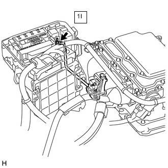
INSPECT POWER MANAGEMENT CONTROL ECU (RESISTANCE VALUE OF NODD INSIDE POWER MANAGEMENT CONTROL ECU)
-
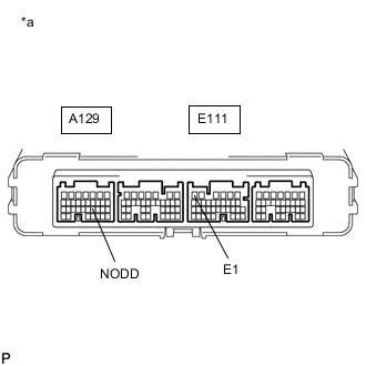
*a Component without harness connected
(Power Management Control ECU)
Disconnect the A129, A130, E111 and E112 power management control ECU connectors.
-
Measure the resistance according to the value(s) in the table below.
Standard Resistance Tester Connection Condition Specified Condition A129-21 (NODD) - E111-6 (E1) Power switch off 110 to 150 kΩ -
Reconnect the A129, A130, E111 and E112 power management control ECU connectors.
Result Proceed to OK NG
OK
REPAIR OR REPLACE HARNESS OR CONNECTOR
NG
REPLACE POWER MANAGEMENT CONTROL ECU for LHD: Click here
REPLACE POWER MANAGEMENT CONTROL ECU for RHD: Click here -
-
CHECK HYBRID VEHICLE TRANSAXLE ASSEMBLY (MG1)
CAUTION:
Be sure to wear insulated gloves.
-
Check that the service plug grip is not installed.
Note
After removing the service plug grip, do not turn the power switch on (READY), unless instructed by the repair manual because this may cause a malfunction.
-
Remove the inverter cover from the inverter with converter assembly.
-
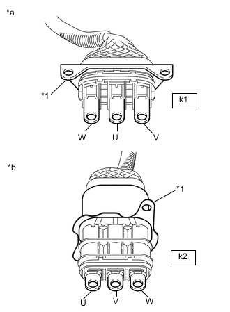
*1 Generator Cable
(Inverter with Converter Assembly Side)
Disconnect the generator cable from the inverter with converter assembly.
-
*1 Shield Ground *a Generator Cable (Inverter with Converter Assembly Side) Using a megohmmeter set to 500 V, measure the insulation resistance according to the value(s) in the table below.
Note
Be sure to set the megohmmeter to 500 V when performing this test. Using a setting higher than 500 V can result in damage to the component being inspected.
Standard Resistance Tester Connection Condition Specified Condition m1-1 (W) - Body ground and shield ground Power switch off 100 MΩ or higher m1-2 (U) - Body ground and shield ground Power switch off 100 MΩ or higher m1-3 (V) - Body ground and shield ground Power switch off 100 MΩ or higher -
Connect the generator cable.
-
Install the inverter cover.
Result Proceed to OK NG
NG
CHECK HYBRID VEHICLE TRANSAXLE ASSEMBLY (GENERATOR CABLE CONNECTION CONDITION) Click here
OK
-
-
CHECK HYBRID VEHICLE TRANSAXLE ASSEMBLY (MG2)
CAUTION:
Be sure to wear insulated gloves.
-
Check that the service plug grip is not installed.
Note
After removing the service plug grip, do not turn the power switch on (READY), unless instructed by the repair manual because this may cause a malfunction.
-
Remove the inverter cover from the inverter with converter assembly.
-
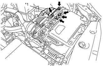
*1 Motor Cable
(Inverter with Converter Assembly Side)
Disconnect the motor cable from the inverter with converter assembly.
-
*1 Shield Ground *a Motor Cable
(Inverter with Converter Assembly Side)
Using a megohmmeter set to 500 V, measure the insulation resistance according to the value(s) in the table below.
Note
Be sure to set the megohmmeter to 500 V when performing this test. Using a setting higher than 500 V can result in damage to the component being inspected.
Standard Resistance Tester Connection Condition Specified Condition k1-1 (W) - Body ground and shield ground Power switch off 100 MΩ or higher k1-2 (U) - Body ground and shield ground Power switch off 100 MΩ or higher k1-3 (V) - Body ground and shield ground Power switch off 100 MΩ or higher -
Connect the motor cable.
-
Install the inverter cover.
Result Proceed to OK NG
OK
REFER TO REPLACE INVERTER WITH CONVERTER ASSEMBLY PARTS Click here
NG
-
-
CHECK HYBRID VEHICLE TRANSAXLE ASSEMBLY (MOTOR CABLE CONNECTION CONDITION)
Result Proceed to A B C CAUTION:
Be sure to wear insulated gloves.
-
Check that the service plug grip is not installed.
Note
After removing the service plug grip, do not turn the power switch on (READY), unless instructed by the repair manual because this may cause a malfunction.
-
Check that the bolts for the motor cable are tightened to the specified torque, the motor cable is connected securely, and there are no contact problems.
Specified Condition T = 10 N*m (102 kgf*cm, 7 ft.*lbf) Note
Make sure that the tightening torque of the bolt is between 8 and 12 N*m (82 and 122 kgf*cm, 71 and 106 in.*lbf).
-
Disconnect the motor cable from the hybrid vehicle transaxle assembly.
-
Check for arc marks at the terminals for the motor cable.
Result Result Proceed to The terminals are connected securely and there are no contact problems. There are no arc marks. A The terminals are not connected securely and there is a contact problem. There are arc marks. B The terminals are not connected securely and there is a contact problem. There are no arc marks. C The terminals are connected securely and there are no contact problems. There are arc marks. B -
Connect the motor cable to the hybrid vehicle transaxle assembly.
B
REPLACE MALFUNCTIONING PARTS
C
CONNECT SECURELY
A
-
-
CHECK MOTOR CABLE
Result Result OK NG CAUTION:
Be sure to wear insulated gloves.
-
Check that the service plug grip is not installed.
Note
After removing the service plug grip, do not turn the power switch on (READY), unless instructed by the repair manual because this may cause a malfunction.
-
Remove the motor cable.
-
*1 Shield ground *a Motor Cable
(Inverter with Converter Assembly Side)
*b Motor Cable
(Hybrid Vehicle Transaxle Assembly Side)
Using a megohmmeter set to 500 V, measure the resistance according to the value(s) in the table below.
Note
Be sure to set the megohmmeter to 500 V when performing this test. Using a setting higher than 500 V can result in damage to the component being inspected.
Standard Resistance Tester Connection Condition Specified Condition k1-1 (W) - Body ground and shield ground Power switch off 100 MΩ or higher k1-2 (U) - Body ground and shield ground Power switch off 100 MΩ or higher k1-3 (V) - Body ground and shield ground Power switch off 100 MΩ or higher Note
Wrap the terminal of the motor cable with insulating tape to prevent them from coming into contact with body ground.
-
Measure the resistance according to the value(s) in the table below.
Standard Resistance Tester Connection Condition Specified Condition k1-1 (W) - k2-3 (U) Power switch off 100 MΩ or higher k1-2 (U) - k2-2 (V) Power switch off 100 MΩ or higher k1-3 (V) - k2-1 (W) Power switch off 100 MΩ or higher k1-1 (W) - k2-1 (W) Power switch off Below 1 Ω k1-2 (U) - k2-3 (U) Power switch off Below 1 Ω k1-3 (V) - k2-2 (V) Power switch off Below 1 Ω -
Install the motor cable.
Result Proceed to OK NG
OK
REPLACE HYBRID VEHICLE MOTOR ASSEMBLY Click here
NG
REPLACE MOTOR CABLE Click here
-
-
CHECK NO. 1 ENGINE ROOM RELAY BLOCK AND NO. 1 JUNCTION BLOCK ASSEMBLY (IGCT RELAY, IGCT FUSE, IGCT NO. 2 FUSE)
-
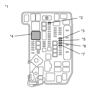
*1 No. 1 Engine Room Relay Block and No. 1 Junction Block Assembly *2 IGCT-MAIN Fuse *3 IGCT NO. 2 Fuse *4 IGCT Relay *5 INV W/PMP Fuse *6 PCU Fuse *7 PM-IGCT Fuse Remove the IGCT relay, IGCT-MAIN fuse, IGCT NO. 2 fuse, INV W/PMP fuse, PCU fuse and PM-IGCT fuse from the No. 1 engine room relay block and No. 1 junction block assembly.
-
*1 No. 1 Engine Room Relay Block and No. 1 Junction Block Assembly *2 IGCT Relay Measure the resistance according to the value(s) in the table below.
Standard Resistance Tester Connection Condition Specified Condition 3 (IGCT relay) - Body ground and other terminals Always 10 kΩ or higher 5 (IGCT relay) - Body ground and other terminals Always 10 kΩ or higher -
Install the IGCT relay, IGCT-MAIN fuse, IGCT NO. 2 fuse, INV W/PMP fuse, PCU fuse and PM-IGCT fuse.
Result Proceed to OK NG
OK
REPLACE FUSE (IGCT-MAIN)
NG
-
-
REPAIR OR REPLACE NO. 1 ENGINE ROOM RELAY BLOCK AND NO. 1 JUNCTION BLOCK ASSEMBLY
Result Proceed to NEXT
NEXT
REPLACE FUSE (IGCT-MAIN)
-
CHECK HYBRID VEHICLE TRANSAXLE ASSEMBLY (GENERATOR CABLE CONNECTION CONDITION)
Result Proceed to A B C CAUTION:
Be sure to wear insulated gloves.
-
Check that the service plug grip is not installed.
Note
After removing the service plug grip, do not turn the power switch on (READY), unless instructed by the repair manual because this may cause a malfunction.
-
Remove the inverter with converter assembly.
-
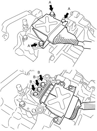
Check that the bolts for the generator cable are tightened to the specified torque, the generator cable is connected securely, and there are no contact problems.
Specified Condition Bolt A T = 20 N*m (204 kgf*cm, 15 ft.*lbf) Bolt B T = 10 N*m (102 kgf*cm, 7 ft.*lbf) Note
-
Make sure that the tightening torque of the bolt A is between 16 and 24 N*m (163 to 245 kgf*cm, 12 to 18 ft.*lbf).
-
Make sure that the tightening torque of the bolt B is between 8 and 12 N*m (82 and 122 kgf*cm, 71 and 106 in.*lbf).
-
-
Disconnect the generator cable from the hybrid vehicle transaxle assembly.
-
Check for arc marks at the terminals for the generator cable.
Result Result Proceed to The terminals are connected securely and there are no contact problems. There are no arc marks. A The terminals are not connected securely and there is a contact problem. There are arc marks. B The terminals are not connected securely and there is a contact problem. There are no arc marks. C The terminals are connected securely and there are no contact problems. There are arc marks. B -
Connect the generator cable to the hybrid vehicle transaxle assembly.
-
Install the inverter with converter assembly.
B
REPLACE MALFUNCTIONING PARTS
C
CONNECT SECURELY
A
-
-
CHECK GENERATOR CABLE
Result Result OK NG CAUTION:
Be sure to wear insulated gloves.
-
Check that the service plug grip is not installed.
Note
After removing the service plug grip, do not turn the power switch on (READY), unless instructed by the repair manual because this may cause a malfunction.
-
Remove the generator cable.
-
*1 Shield ground *a Generator Cable
(Inverter with Converter Assembly Side)
*b Generator Cable
(Hybrid Vehicle Transaxle Assembly Side)
Using a megohmmeter set to 500 V, measure the resistance according to the value(s) in the table below.
Note
Be sure to set the megohmmeter to 500 V when performing this test. Using a setting higher than 500 V can result in damage to the component being inspected.
Standard Resistance Tester Connection Condition Specified Condition m1-1 (W) - Body ground and shield ground Power switch off 100 MΩ or higher m1-2 (U) - Body ground and shield ground Power switch off 100 MΩ or higher m1-3 (V) - Body ground and shield ground Power switch off 100 MΩ or higher Note
Wrap the terminal of the generator cable with insulating tape to prevent them from coming into contact with body ground.
-
Measure the resistance according to the value(s) in the table below.
Standard Resistance Tester Connection Condition Specified Condition m1-1 (W) - m2-2 (U) Power switch off 100 MΩ or higher m1-2 (U) - m2-1 (V) Power switch off 100 MΩ or higher m1-3 (V) - m2-3 (W) Power switch off 100 MΩ or higher m1-1 (W) - m2-3 (W) Power switch off Below 1 Ω m1-2 (U) - m2-2 (U) Power switch off Below 1 Ω m1-3 (V) - m2-1 (V) Power switch off Below 1 Ω -
Install the generator cable.
Result Proceed to OK NG
OK
REPLACE HYBRID VEHICLE GENERATOR ASSEMBLY Click here
NG
REPLACE GENERATOR CABLE Click here
-
-
CHECK HARNESS AND CONNECTOR (INVERTER WITH CONVERTER ASSEMBLY - DC/DC-S FUSE)
CAUTION:
Be sure to wear insulated gloves.
-
Check that the service plug grip is not installed.
Note
After removing the service plug grip, do not turn the power switch on (READY), unless instructed by the repair manual because this may cause a malfunction.
-
Disconnect the A143 inverter with converter assembly connector.
-
*1 No. 1 Engine Room Relay Block and No. 1 Junction Block Assembly *2 DC/DC-S Fuse Remove the DC/DC-S fuse from the No. 1 engine room relay block and No. 1 junction block assembly.
-
Measure the resistance according to the value(s) in the table below.
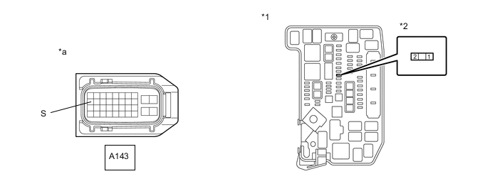
*1 No. 1 Engine Room Relay Block and No. 1 Junction Block Assembly *2 DC/DC-S Fuse *a Front view of wire harness connector
(to Inverter with Converter Assembly)
- - Standard Resistance Tester Connection Condition Specified Condition A143-11 (S) or 2 (DC/DC-S fuse) - Body ground and other terminals Power switch off 10 kΩ or higher -
Install the DC/DC-S fuse.
-
Reconnect the A143 inverter with converter assembly connector.
Result Proceed to OK NG
NG
REPAIR OR REPLACE HARNESS OR CONNECTOR Click here
OK
-
-
REFER TO REPLACE INVERTER WITH CONVERTER ASSEMBLY PARTS
Result Proceed to NEXT
NEXT
REPLACE FUSE (DC/DC-S)
-
REPAIR OR REPLACE HARNESS OR CONNECTOR
Result Proceed to NEXT
NEXT
REPLACE FUSE (DC/DC-S)
-
CHECK HARNESS AND CONNECTOR (INVERTER WITH CONVERTER ASSEMBLY - IGCT NO. 2 FUSE)
CAUTION:
Be sure to wear insulated gloves.
-
Check that the service plug grip is not installed.
Note
After removing the service plug grip, do not turn the power switch on (READY), unless instructed by the repair manual because this may cause a malfunction.
-
Disconnect the A143 inverter with converter assembly connector.
-
Disconnect the A131 transmission control ECU assembly connector.
-
Disconnect the L48 battery voltage sensor connector.
-
*1 No. 1 Engine Room Relay Block and No. 1 Junction Block Assembly *2 IGCT NO. 2 Fuse Remove the IGCT NO. 2 fuse from the No. 1 engine room relay block and No. 1 junction block assembly.
-
Measure the resistance according to the value(s) in the table below.
*1 No. 1 Engine Room Relay Block and No. 1 Junction Block Assembly *2 IGCT NO. 2 Fuse *a Front view of wire harness connector
(to Inverter with Converter Assembly)
- - Standard Resistance Tester Connection Condition Specified Condition A143-1 (IGCT) or 2 (IGCT NO. 2 fuse) - Body ground and other terminals Power switch off 10 kΩ or higher -
Install the IGCT NO. 2 fuse.
-
Reconnect the L48 battery voltage sensor connector.
-
Reconnect the A131 transmission control ECU assembly connector.
-
Reconnect the A143 inverter with converter assembly connector.
Result Proceed to OK NG
NG
REPAIR OR REPLACE HARNESS OR CONNECTOR Click here
OK
-
-
REFER TO REPLACE INVERTER WITH CONVERTER ASSEMBLY PARTS
Result Proceed to NEXT
NEXT
REPLACE FUSE (IGCT NO. 2)
-
REPAIR OR REPLACE HARNESS OR CONNECTOR
Result Proceed to NEXT
NEXT
REPLACE FUSE (IGCT NO. 2)