HYBRID CONTROL SYSTEM, Diagnostic DTC:P0851-579, P0852-580
| DTC Code | DTC Name |
|---|---|
| P0851-579 | Park / Neutral Switch Input Circuit Low |
| P0852-580 | Park / Neutral Switch Input Circuit High |
DESCRIPTION
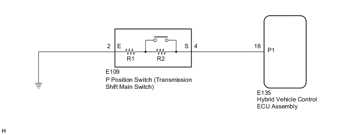
Instead of having a parking position as one of the positions as on a conventional shift lever, a P position switch (transmission shift main switch) is provided independently above the shift lever. The switch is a momentary type, in which the button does not lock mechanically.
The P position switch (transmission shift main switch) contains resistors R1 and R2. When the P position switch (transmission shift main switch) is not pressed, the switch provides a combined resistance of R1 and R2; and when the P position switch (transmission shift main switch) is pressed, the switch provides only the resistance of R1. The voltage at the P1 terminal of the hybrid vehicle control ECU assembly varies with the changes in the resistance of the switch. The hybrid vehicle control ECU assembly determines the P position switch (transmission shift main switch) operation according to this resistance signal.
| DTC No. | Detection Item | DTC Detection Condition | Trouble Area | MIL | Warning Indicate |
|---|---|---|---|---|---|
| P0851-579 | Park / Neutral Switch Input Circuit Low | GND short in P position switch circuit |
|
Does not come on | Master Warning Light: Comes on |
| P0852-580 | Park / Neutral Switch Input Circuit High | Open or +B short in P position switch circuit |
|
Does not come on | Master Warning Light: Comes on |
WIRING DIAGRAM
PROCEDURE
-
INSPECT P POSITION SWITCH (TRANSMISSION SHIFT MAIN SWITCH)
-
Disconnect the E109 P position switch (transmission shift main switch) connector.
-
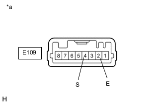
*a Component without harness connected
(P Position Switch (Transmission Shift Main Switch))
Measure the resistance according to the value(s) in the table below.
Standard Resistance Tester Connection Condition Specified Condition E109-4 (S) - E109-2 (E) Switch pressed 680 Ω E109-4 (S) - E109-2 (E) Switch released 4580 Ω Tech Tips
Terminals No. 1 and No. 8 on the component side connector are empty.
-
Reconnect the E109 P position switch (transmission shift main switch) connector.
Result Proceed to OK NG
NG 
REPLACE P POSITION SWITCH (TRANSMISSION SHIFT MAIN SWITCH)
OK 
-
-
CHECK HARNESS AND CONNECTOR (HYBRID VEHICLE CONTROL ECU ASSEMBLY - P POSITION SWITCH (TRANSMISSION SHIFT MAIN SWITCH))
-
Disconnect the E135 hybrid vehicle control ECU assembly connector.
-
Disconnect the E109 P position switch (transmission shift main switch) connector.
-
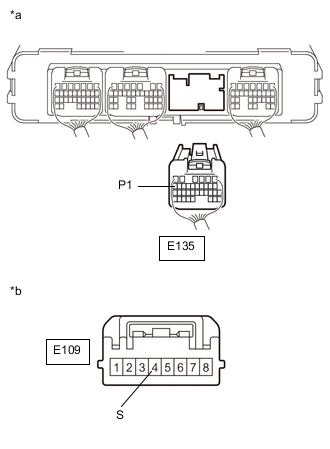
*a Rear view of wire harness connector
(to Hybrid Vehicle Control ECU Assembly)
*b Front view of wire harness connector
(to P Position Switch (Transmission Shift Main Switch))
Measure the resistance according to the value(s) in the table below.
Standard Resistance (Check for Open) Tester Connection Condition Specified Condition E135-16 (P1) - E109-4 (S) Power switch off Below 1 Ω Standard Resistance (Check for Short) Tester Connection Condition Specified Condition E135-16 (P1) or E109-4 (S) - Body ground and other terminals Power switch off 10 kΩ or higher Tech Tips
As necessary, check that there is no short to power supply wires when performing the above wire harness inspection.
-
Reconnect the E109 P position switch (transmission shift main switch) connector.
-
Reconnect the E135 hybrid vehicle control ECU assembly connector.
Result Proceed to OK NG
NG
REPAIR OR REPLACE HARNESS OR CONNECTOR
OK
-
-
CHECK HARNESS AND CONNECTOR (P POSITION SWITCH (TRANSMISSION SHIFT MAIN SWITCH) - BODY GROUND)
-
Disconnect the E109 P position switch (transmission shift main switch) connector.
-
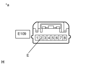
*a Front view of wire harness connector
(to P Position Switch (Transmission Shift Main Switch))
Measure the resistance according to the value(s) in the table below.
Standard Resistance (Check for Open) Tester Connection Condition Specified Condition E109-2 (E) - Body ground Power switch off Below 1 Ω -
Reconnect the E109 P position switch (transmission shift main switch) connector.
Result Proceed to OK NG
OK
REPLACE HYBRID VEHICLE CONTROL ECU ASSEMBLY for LHD: Click here
REPLACE HYBRID VEHICLE CONTROL ECU ASSEMBLY for RHD: Click hereNG
REPAIR OR REPLACE HARNESS OR CONNECTOR
-