SFI SYSTEM Fuel Pump Control Circuit
DESCRIPTION
When the engine is cranked, the start request signal output from the hybrid vehicle control ECU assembly is input to the ECM, and the NE signal generated by the crank position sensor is also input to the NE+ terminal. Thus, the ECM interprets that the engine has been cranked, and turns transistor Tr in the ECM internal circuit on. Current flows to the C/OPN (Circuit Opening) relay by turning Tr on. Then, the fuel pump operates.
While the NE signal is input to the ECM with the engine running, the ECM turns Tr on continuously.
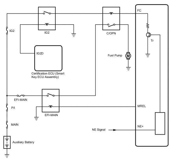
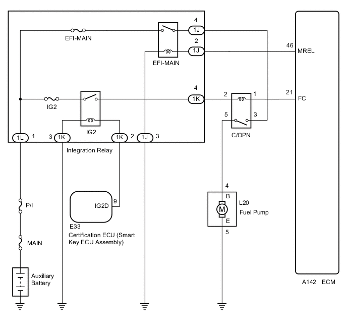
WIRING DIAGRAM
CAUTION / NOTICE / HINT
Note
Inspect the fuses for circuits related to this system before performing the following procedure.
PROCEDURE
-
PERFORM ACTIVE TEST USING GTS (CONTROL THE FUEL PUMP / SPEED)
-
Connect the GTS to the DLC3.
-
Turn the power switch on (IG).
-
Turn the GTS on.
-
Enter the following menus: Powertrain / Engine and ECT / Active Test / Control the Fuel Pump / Speed.
Powertrain > Engine and ECT > Active TestTester Display Control the Fuel Pump / Speed -
Check whether the fuel pump operating sound occurs when performing the Active Test on the GTS.
Result Result Proceed to Fuel pump operating sound does not occur A Fuel pump operating sound occurs B
B 
READ VALUE USING GTS (STARTER SIGNAL) Click here
A 
-
-
INSPECT RELAY (C/OPN RELAY)
-
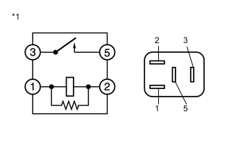
*1 C/OPN Relay Remove the C/OPN relay from the No. 1 engine room relay block and No. 1 junction block assembly.
-
Measure the resistance according to the value(s) in the table below.
Standard Resistance Tester Connection Condition Specified Condition 3 - 5 No auxiliary battery voltage applied between terminals 1 and 2 10 kΩ or higher 3 - 5 Auxiliary battery voltage applied between terminals 1 and 2 Below 1 Ω Result Proceed to OK NG
NG 
REPLACE RELAY (C/OPN RELAY])
OK
-
-
CHECK HARNESS AND CONNECTOR (C/OPN RELAY - ECM)
-
Remove the C/OPN relay from the No. 1 engine room relay block and No. 1 junction block assembly.
-
Disconnect the ECM connector.
-
Measure the resistance according to the value(s) in the table below.
Standard Resistance Tester Connection Condition Specified Condition C/OPN relay terminal 1 - A142-21 (FC) Always Below 1 Ω C/OPN relay terminal 1 or A142-21 (FC) - Body ground Always 10 kΩ or higher Result Proceed to OK NG
NG
REPAIR OR REPLACE HARNESS OR CONNECTOR
OK
-
-
CHECK HARNESS AND CONNECTOR (C/OPN RELAY - INTEGRATION RELAY (IG2 RELAY))
-
Remove the C/OPN relay from the No. 1 engine room relay block and No. 1 junction block assembly.
-
Remove the integration relay (IG2 relay) from the No. 1 engine room relay block and No. 1 junction block assembly.
-
Measure the resistance according to the value(s) in the table below.
Standard Resistance Tester Connection Condition Specified Condition C/OPN relay terminal 2 - 1K-4 Always Below 1 Ω C/OPN relay terminal 2 or 1K-4 - Body ground Always 10 kΩ or higher Result Proceed to OK NG
NG
REPAIR OR REPLACE HARNESS OR CONNECTOR
OK
-
-
CHECK HARNESS AND CONNECTOR (C/OPN RELAY - FUEL PUMP)
-
Remove the C/OPN relay from the No. 1 engine room relay block and No. 1 junction block assembly.
-
Disconnect the fuel pump connector.
-
Measure the resistance according to the value(s) in the table below.
Standard Resistance Tester Connection Condition Specified Condition C/OPN relay terminal 5 - L20-4 (B) Always Below 1 Ω C/OPN relay terminal 5 or L20-4 (B) - Body ground Always 10 kΩ or higher Result Proceed to OK NG
NG
REPAIR OR REPLACE HARNESS OR CONNECTOR
OK
-
-
CHECK HARNESS AND CONNECTOR (FUEL PUMP - BODY GROUND)
-
Disconnect the fuel pump connector.
-
Measure the resistance according to the value(s) in the table below.
Standard Resistance Tester Connection Condition Specified Condition L20-5 (E) - Body ground Always Below 1 Ω Result Proceed to OK NG
NG
REPAIR OR REPLACE HARNESS OR CONNECTOR
OK
-
-
INSPECT FUEL PUMP
-
Inspect the fuel pump.
Result Proceed to OK NG
NG
REPLACE FUEL PUMP Click here
OK
-
-
CHECK HARNESS AND CONNECTOR (C/OPN RELAY - INTEGRATION RELAY (EFI-MAIN RELAY))
-
Remove the C/OPN relay from the No. 1 engine room relay block and No. 1 junction block assembly.
-
Remove the integration relay (EFI-MAIN relay) from the No. 1 engine room relay block and No. 1 junction block assembly.
-
Measure the resistance according to the value(s) in the table below.
Standard Resistance Tester Connection Condition Specified Condition C/OPN relay terminal 3 - 1J-4 Always Below 1 Ω C/OPN relay terminal 3 or 1J-4 - Body ground Always 10 kΩ or higher Result Proceed to OK NG
OK
GO TO ECM POWER SOURCE CIRCUIT Click here
NG
REPAIR OR REPLACE HARNESS OR CONNECTOR (INTEGRATION RELAY - AUXILIARY BATTERY)
-
-
READ VALUE USING GTS (STARTER SIGNAL)
-
Connect the GTS to the DLC3.
-
Turn the power switch on (IG).
-
Turn the GTS on.
-
Put the engine in inspection mode (maintenance mode).
-
Enter the following menus: Powertrain / Engine and ECT / Data List / All Data / Starter Signal.
Powertrain > Engine and ECT > Data ListTester Display Starter Signal -
Check the result when the power switch on (IG) and the engine starts.
OK Condition Starter Signal Power switch on (IG) OFF Engine Started ON Result Proceed to OK NG
NG
GO TO HYBRID CONTROL SYSTEM Click here
OK
-
-
READ VALUE USING GTS (ENGINE SPEED)
-
Connect the GTS to the DLC3.
-
Turn the power switch on (IG).
-
Turn the GTS on.
-
Put the engine in inspection mode (maintenance mode).
-
Enter the following menus: Powertrain / Engine and ECT / Data List / All Data / Engine Speed.
Powertrain > Engine and ECT > Data ListTester Display Engine Speed -
Read the values displayed on the GTS while cranking.
OK Values are displayed continuously. Result Proceed to OK NG
OK
PROCEED TO NEXT SUSPECTED AREA SHOWN IN PROBLEM SYMPTOMS TABLE Click here
NG
CHECK CRANK POSITION SENSOR CIRCUIT Click here
-