REAR AXLE CARRIER REMOVAL
CAUTION / NOTICE / HINT
Note
When the brake pedal is first depressed after replacing the brake pads or pushing back the disc brake piston, DTC C1214 may be output. As there is no malfunction, clear the DTC.
Tech Tips
-
Use the same procedure for the RH side and LH side.
-
The procedure listed below is for the LH side.
PROCEDURE
-
PRECAUTION
Note
After turning the power switch off, waiting time may be required before disconnecting the cable from the negative (-) auxiliary battery terminal. Therefore, make sure to read the disconnecting the cable from the negative (-) auxiliary battery terminal notice before proceeding with work.
-
DISABLE BRAKE CONTROL
-
REMOVE REAR WHEEL
-
REMOVE UPPER CONSOLE PANEL SUB-ASSEMBLY
-
LOOSEN NO. 2 WIRE ADJUSTING NUT
-
REMOVE REAR SUSPENSION ARM COVER
-
REMOVE REAR FLOOR SIDE MEMBER COVER LH (for LH Side)
-
REMOVE REAR FLOOR SIDE MEMBER COVER RH (for RH Side)
-
REMOVE PARKING BRAKE LEVER PROTECTOR
-
SEPARATE NO. 3 PARKING BRAKE CABLE ASSEMBLY
-
SEPARATE REAR DISC BRAKE CALIPER ASSEMBLY
-
REMOVE REAR DISC
-
REMOVE REAR HEIGHT CONTROL SENSOR SUB-ASSEMBLY (w/ Height Control Sensor)
-
DISCONNECT SKID CONTROL SENSOR WIRE
-
REMOVE REAR AXLE HUB AND BEARING ASSEMBLY
-
REMOVE REAR NO. 1 SUSPENSION ARM ASSEMBLY
-
REMOVE REAR AXLE CARRIER SUB-ASSEMBLY
-
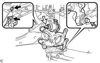

Bolt (A) 
Bolt (B) 
Bolt (C) Loosen the 2 bolts (A), bolt (B) and bolt (C).
Note
-
Because the nuts have their own stoppers, do not turn the nuts. Loosen the bolts with the nuts secured.
-
Do not remove the bolts.
-
-
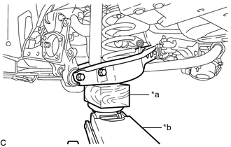
*a Wooden Block *b Jack Using a jack and wooden block, keep the rear No. 2 suspension arm assembly level.
CAUTION:
Do not jack up the rear No. 2 suspension arm assembly too high as the vehicle may fall.
Note
-
When jacking up the rear No. 2 suspension arm assembly, be sure to jack it up slowly.
-
Make sure to perform this operation with the vehicle kept as low as possible.
-
-
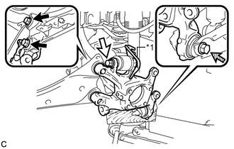
*1 No. 2 Flexible Hose Bracket Bolt (A) Bolt (B) Bolt (C) Remove the 2 bolts (A), and separate the rear trailing arm assembly from the rear axle carrier sub-assembly.
-
Remove the bolt (B), nut and No. 2 flexible hose bracket, and then separate the rear upper control arm assembly from the rear axle carrier sub-assembly.
Note
Because the nut has its own stopper, do not turn the nut. Loosen the bolt with the nut secured.
-
Remove the bolt (C), nut and rear axle carrier sub-assembly from the rear No. 2 suspension arm assembly.
Note
Because the nut has its own stopper, do not turn the nut. Loosen the bolt with the nut secured.
-