HYBRID VEHICLE TRANSAXLE INSTALLATION
PROCEDURE
-
INSTALL MOTOR CABLE BRACKET
-
Install the motor cable bracket to the hybrid vehicle transaxle assembly with the bolt.
- Torque:
- 23 N*m { 235 kgf*cm, 17 ft.*lbf }
-
-
INSTALL WIRE HARNESS CLAMP BRACKET
-
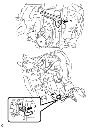
Install the 2 wire harness clamp brackets to the hybrid vehicle transaxle assembly with the 2 bolts.
- Torque:
- Bolt A
- 12.5 N*m { 127 kgf*cm, 9 ft.*lbf }
- Bolt B
- 8.0 N*m { 82 kgf*cm, 71 in.*lbf }
-
-
INSTALL MOTOR CABLE
-
INSTALL GENERATOR CABLE
-
INSTALL REAR ENGINE MOUNTING BRACKET
-
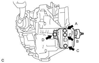
Install the rear engine mounting bracket to the hybrid vehicle transaxle assembly with the 4 bolts in several steps.
- Torque:
- 45 N*m { 459 kgf*cm, 33 ft.*lbf }
Note
Temporarily tighten the bolt (A), and then fully tighten the 4 bolts in the order of (C), (D), (B) and (A).
-
-
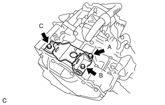
INSTALL FRONT ENGINE MOUNTING BRACKET
-
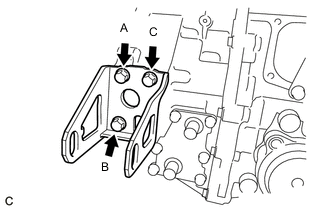
Install the front engine mounting bracket to the hybrid vehicle transaxle assembly with the 3 bolts in several steps.
- Torque:
- Green Bolt
- 64 N*m { 653 kgf*cm, 47 ft.*lbf }
- Silver Bolt
- 45 N*m { 459 kgf*cm, 33 ft.*lbf }
Note
Temporarily tighten the bolt (A), and then fully tighten the 3 bolts in the order of (B), (C) and (A).
-
-
INSTALL HYBRID VEHICLE TRANSAXLE ASSEMBLY
-
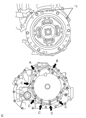
*1 Knock Pin Make sure that the 2 knock pins are installed to the engine assembly.
-
Using a transmission jack, align the engine assembly and hybrid vehicle transaxle assembly, fit the knock pins into the knock pin holes, and tighten the 7 bolts shown in the illustration.
- Torque:
- 33 N*m { 337 kgf*cm, 24 ft.*lbf }
Note
-
Make sure to align the hybrid vehicle transaxle assembly so that the input shaft of the hybrid vehicle transaxle assembly will be inserted straight into the inner splines of the transmission input damper.
-
When inserting the input shaft of the hybrid vehicle transaxle assembly into the inner splines of the transmission input damper, do not shake the hybrid vehicle transaxle assembly excessively.
-
When mounting the hybrid vehicle transaxle assembly to the engine assembly, make sure to securely fit the knock pins into the knock pin holes.
-
Push in the hybrid vehicle transaxle assembly so that the contact surfaces of the engine assembly and hybrid vehicle transaxle assembly are aligned evenly.
-
While mounting the hybrid vehicle transaxle assembly to the engine assembly, temporarily tighten the bolt (A), and then fully tighten the 3 bolts in the order of (B), (A) and (C).
-
Do not hang the hybrid vehicle transaxle assembly off of the engine assembly if the contact surfaces of the engine assembly and hybrid vehicle transaxle assembly are not in full contact. The knock pin holes of the hybrid vehicle transaxle case may be deformed due to the excessive weight of the engine assembly and hybrid vehicle transaxle assembly, resulting in misalignment between the engine assembly and hybrid vehicle transaxle assembly.
-
-
INSTALL ENGINE MOUNTING BRACKET LH
-
Install the engine mounting bracket LH to the hybrid vehicle transaxle assembly with 3 new bolts in several steps.
- Torque:
- 64 N*m { 653 kgf*cm, 47 ft.*lbf }
Note
Temporarily tighten the bolt (A), and then fully tighten the 3 bolts in the order of (B), (C) and (A).
-
Install the engine mounting insulator LH to the engine mounting bracket LH with the bolt and nut.
- Torque:
- 56 N*m { 571 kgf*cm, 41 ft.*lbf }
Note
When installing the engine mounting insulator LH, tighten the nut while holding the bolt.
-
-
INSTALL FLYWHEEL HOUSING SIDE COVER
-
Install the flywheel housing side cover to the engine assembly.
-
-
INSTALL STARTER HOLE INSULATOR
-
Install the starter hole insulator to the engine assembly with the 2 bolts.
- Torque:
- 37 N*m { 377 kgf*cm, 27 ft.*lbf }
-
-
CONNECT WIRE HARNESS
-
Connect the 12 wire harness clamps and install the 2 bolts.
- Torque:
- 8.0 N*m { 82 kgf*cm, 71 in.*lbf }
-
Connect the engine coolant temperature sensor connector.
-
Connect the generator cable terminal connector.
-
Connect the motor cable terminal connector.
-
Connect the resolver sensor connector.
-
Connect the shift control actuator assembly connector.
-
Connect the throttle body assembly connector.
-
-
INSTALL RADIATOR PIPE
-
TEMPORARILY TIGHTEN REAR ENGINE MOUNTING INSULATOR
-
TEMPORARILY TIGHTEN FRONT ENGINE MOUNTING INSULATOR
-
INSTALL ENGINE ASSEMBLY WITH TRANSAXLE