ELECTRONIC SHIFT LEVER SYSTEM, Diagnostic DTC:C2307
| DTC Code | DTC Name |
|---|---|
| C2307 | Power Supply |
DESCRIPTION
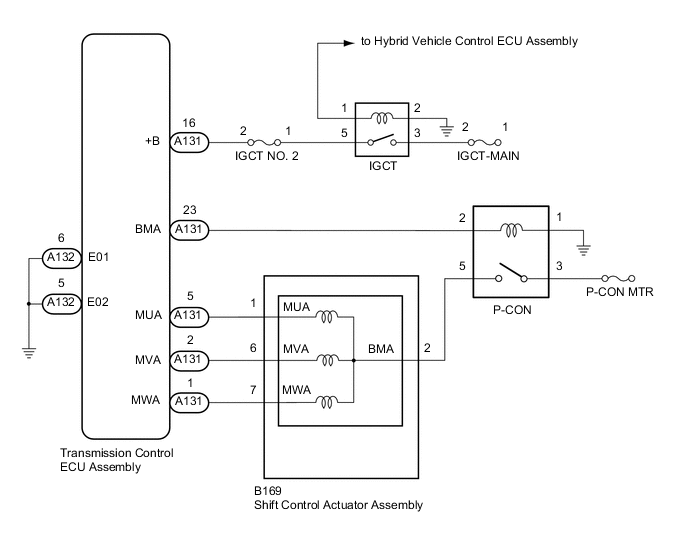
The shift control actuator assembly consists of a parking lock motor and rotation angle sensor. The transmission control ECU assembly receives a P position switch signal from the hybrid vehicle control ECU assembly and activates the parking lock motor by controlling current, causing the parking lock mechanism to switch. The transmission control ECU assembly stores this DTC when it detects a malfunction in the parking lock motor system and/or the ground circuit.
| DTC No. | Detection Item | DTC Detection Condition | Trouble Area | Warning Indicate | Memory |
|---|---|---|---|---|---|
| C2307 | Power Supply | With the power switch on (IG) (IG circuit malfunction is not detected), current of the parking lock motor is 50 A or more or there is an open in the transmission control ECU assembly terminal E01 and E02 circuits for 0.1 seconds or more. |
|
|
DTC stored |
WIRING DIAGRAM
CAUTION / NOTICE / HINT
Note
It may not be possible to clear the following DTCs using the GTS: DTC C2300 (Actuator System Malfunction), C2301 (Shift Changing Time Malfunction), C2303 (Short in Power Source Relay Circuit), C2304 (Open or Short Circuit in U Phase), C2305 (Open or Short Circuit in V Phase), C2306 (Open or Short Circuit in W Phase), C2307 (Power Supply) and C2309 (Open in B+ Circuit). In such cases, disconnect the P-CON MAIN fuse and wait for at least 60 seconds to clear the DTCs after the repair.
PROCEDURE
-
CHECK HARNESS AND CONNECTOR (TRANSMISSION CONTROL ECU ASSEMBLY - BODY GROUND)
-
Disconnect the A132 transmission control ECU assembly connector.
-
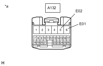
*a Front view of wire harness connector
(to Transmission Control ECU Assembly)
Measure the resistance according to the value(s) in the table below.
Standard Resistance (Check for Open) Tester Connection Condition Specified Condition A132-6 (E01) - Body ground Power switch off Below 1 Ω A132-5 (E02) - Body ground Power switch off Below 1 Ω -
Reconnect the A132 transmission control ECU assembly connector.
Result Proceed to OK NG
NG 
REPAIR OR REPLACE HARNESS OR CONNECTOR
OK 
-
-
CHECK HARNESS AND CONNECTOR (TRANSMISSION CONTROL ECU ASSEMBLY - SHIFT CONTROL ACTUATOR ASSEMBLY)
Result Proceed to OK NG
-
Disconnect the A131 transmission control ECU assembly connector.
-
Disconnect the B169 shift control actuator assembly connector.
-
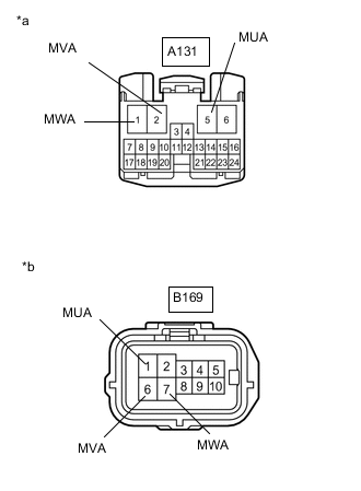
*a Front view of wire harness connector
(to Transmission Control ECU Assembly)
*b Front view of wire harness connector
(to Shift Control Actuator Assembly)
Measure the resistance according to the value(s) in the table below.
Standard Resistance (Check for Short) Tester Connection Condition Specified Condition A131-5 (MUA) or B169-1 (MUA) - Body ground and other terminals Power switch off 10 kΩ or higher A131-2 (MVA) or B169-6 (MVA) - Body ground and other terminals Power switch off 10 kΩ or higher A131-1 (MWA) or B169-7 (MWA) - Body ground and other terminals Power switch off 10 kΩ or higher -
Reconnect the B169 shift control actuator assembly connector.
-
Reconnect the A131 transmission control ECU assembly connector.
Result Proceed to OK NG
OK
REPLACE TRANSMISSION CONTROL ECU ASSEMBLY for LHD: Click here
REPLACE TRANSMISSION CONTROL ECU ASSEMBLY for RHD: Click hereNG
REPAIR OR REPLACE HARNESS OR CONNECTOR
-