ELECTRONIC SHIFT LEVER SYSTEM, Diagnostic DTC:C2311
| DTC Code | DTC Name |
|---|---|
| C2311 | Communication Error from HV ECU |
DESCRIPTION
The transmission control ECU assembly receives a P position switch signal from the power management control ECU and activates the parking lock motor by controlling current, causing the parking lock mechanism to switch. The transmission control ECU assembly stores this DTC when it detects a communication error between the power management control ECU and the transmission control ECU assembly.
| DTC No. | Detection Item | DTC Detection Condition | Trouble Area | Warning Indicate | Memory |
|---|---|---|---|---|---|
| C2311 | Communication Error from HV ECU | With the power switch on (IG) (IG circuit malfunction is not detected), a signal cannot be received from the power management control ECU (open or short in the PCON terminal circuit) or a pulse signal malfunction is received from the power management control ECU for 2 seconds or more. |
|
|
DTC stored |
WIRING DIAGRAM
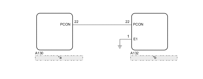
| *a | Power Management Control ECU |
| *b | Transmission Control ECU Assembly |
PROCEDURE
-
CHECK TRANSMISSION CONTROL ECU ASSEMBLY
-
Turn the power switch on (IG).
-
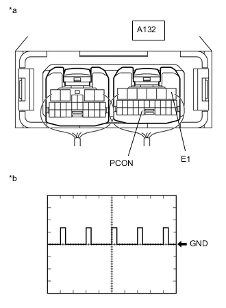
*a Component with harness connected
(Transmission Control ECU Assembly)
*b Waveform Connect an oscilloscope between the transmission control ECU assembly terminals specified in the table below, and measure the waveform.
Item Contents Symbols A132-22 (PCON) - A132-1 (E1) Tool setting 10 V/DIV., 10 msec./DIV. Vehicle condition Power switch on (IG) OK The waveform is similar to that shown in the illustration. Tech Tips
Perform this inspection with the connector connected.
-
Turn the power switch off.
Result Proceed to OK NG
OK 
REPLACE TRANSMISSION CONTROL ECU ASSEMBLY for LHD: Click here
REPLACE TRANSMISSION CONTROL ECU ASSEMBLY for RHD: Click hereNG 
-
-
CHECK HARNESS AND CONNECTOR (TRANSMISSION CONTROL ECU ASSEMBLY - POWER MANAGEMENT CONTROL ECU)
-
Disconnect the A132 transmission control ECU assembly connector.
-
Disconnect the A130 power management control ECU connector.
-
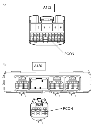
*a Front view of wire harness connector
(to Transmission Control ECU Assembly)
*b Rear view of wire harness connector
(to Power Management Control ECU)
Measure the resistance according to the value(s) in the table below.
Standard Resistance (Check for Open) Tester Connection Condition Specified Condition A132-22 (PCON) - A130-22 (PCON) Power switch off Below 1 Ω Standard Resistance (Check for Short) Tester Connection Condition Specified Condition A132-22 (PCON) or A130-22 (PCON) - Body ground and other terminals Power switch off 10 kΩ or higher -
Reconnect the A130 power management control ECU connector.
-
Reconnect the A132 transmission control ECU assembly connector.
Result Proceed to OK NG
OK
REPLACE POWER MANAGEMENT CONTROL ECU for LHD: Click here
REPLACE POWER MANAGEMENT CONTROL ECU for RHD: Click hereNG
REPAIR OR REPLACE HARNESS OR CONNECTOR
-