ELECTRONIC SHIFT LEVER SYSTEM SYSTEM DESCRIPTION
-
SYSTEM DESCRIPTION
The electronic shift lever system electrically controls the parking lock mechanism using an actuator.
The transmission control ECU assembly locks/unlocks gearshift control based on lock/unlock request signals from the certification ECU (smart key ECU assembly).
The transmission control ECU assembly receives the theft deterrent status (lock or unlock) from the certification ECU (smart key ECU assembly).
Based on this signal, and other information received from the hybrid vehicle control ECU assembly, the transmission control ECU assembly controls the shift control actuator assembly and other parts of the system.
The transmission control ECU assembly detects DTCs when there are any malfunctions in the system, and informs the driver of selected malfunctions by illuminating the master warning light, and indicating an error message on the multi-information display.
Tech Tips
Depending on the DTC that is stored, the master warning light may not illuminate and an error message may not be displayed on the multi-information display.
-
SYSTEM DIAGRAM
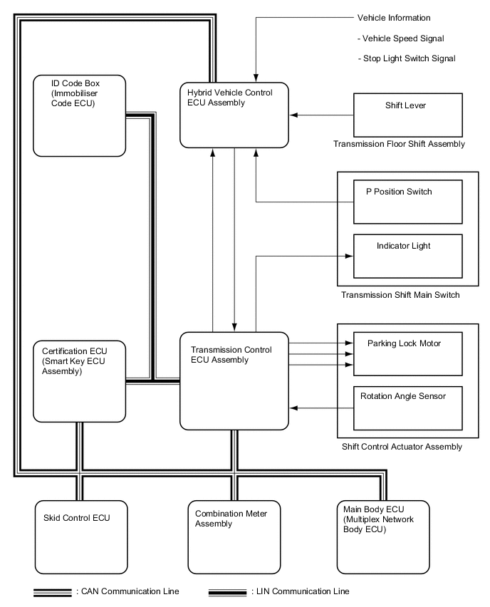
Input and Output Signals of Each ECU Transmitting ECU (Transmitter) Receiving ECU Signal Communication Method Main Body ECU (Multiplex Network Body ECU) Certification ECU (Smart Key ECU Assembly) Parking brake switch signal CAN Main Body ECU (Multiplex Network Body ECU) Transmission Control ECU Assembly
-
Power switch signal
-
ACC switch signal
CAN Transmission Control ECU Assembly Hybrid Vehicle Control ECU Assembly
-
Park (P) state signal
-
Transmission control ECU assembly trouble condition signal
CAN, SIL Certification ECU (Smart Key ECU Assembly) Hybrid Vehicle Control ECU Assembly Auto park (P) request signal CAN Hybrid Vehicle Control ECU Assembly Certification ECU (Smart Key ECU Assembly) Auto park (P) complete signal CAN Transmission Control ECU Assembly Combination Meter Assembly
-
Park (P) state signal
-
Other than park (P) state signal
-
Transmission control ECU assembly trouble condition signal
CAN Hybrid Vehicle Control ECU Assembly Combination Meter Assembly
-
Shift position signal
-
Hybrid vehicle control ECU trouble condition signal
CAN Transmission Control ECU Assembly Certification ECU (Smart Key ECU Assembly) Gear shift control lock state signal LIN -
-
FUNCTION OF EACH COMPONENT
Part Name Function Shift Control Actuator Assembly
-
Composed of a parking lock motor and rotation angle sensor. The motor is activated by electric current from the transmission control ECU assembly.
-
Motor rotation is reduced by the cycloid reduction mechanism in the shift control actuator assembly and then output.
-
The rotation angle sensor detects the motor rotation angle with 2 Hall ICs.
Transmission Control ECU Assembly
-
The transmission control ECU assembly activates the shift control actuator assembly based on signals from the hybrid vehicle control ECU assembly.
-
The transmission control ECU assembly controls the application timing of current to the parking lock motor based on signals from the rotation angle sensor.
Parking Lock Mechanism The parking lock pawl rotates according to the movement of the parking lock rod when the parking lock motor rotates, and engages with the parking gear on the transaxle side, causing the parking lock mechanism to lock or unlock. Hybrid Vehicle Control ECU Assembly The hybrid vehicle control ECU assembly sends a P lock or P unlock demand signal to the transmission control ECU assembly based on information from the shift lever and the P position switch (transmission shift main switch). P Position Switch Indicator Light The P position switch indicator light comes on or goes off to indicate the P lock/unlock status. The P position switch indicator light goes off when the electronic shift lever system malfunctions and an error message is displayed on the multi-information display. Combination Meter Assembly A malfunction in the transmission control ECU assembly is indicated by the illumination of the master warning light on the combination meter assembly. -
-
OPERATION DESCRIPTION
-
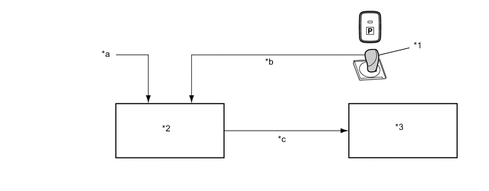
Operation when switching to park (P):
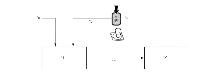
*1 Hybrid Vehicle Control ECU Assembly *2 Transmission Control ECU Assembly *a P Position Switch (Transmission Shift Main Switch) Pushed *b Switch Operation Signal *c Vehicle Speed Signal *d "P Lock" Operation Signal
-
When the P position switch (transmission shift main switch) is pushed to activate the parking lock, a signal is sent to the hybrid vehicle control ECU assembly.
-
The hybrid vehicle control ECU assembly determines whether "P lock" is possible or not based on this signal and other vehicle information.
-
If the hybrid vehicle control ECU assembly determines that "P lock" is possible, it sends a "P lock" operation demand signal to the transmission control ECU assembly.
-
After receiving the signal, the transmission control ECU assembly activates the shift control actuator assembly in order to lock the parking lock mechanism.
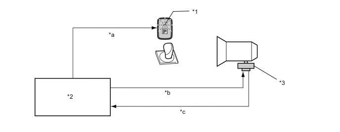
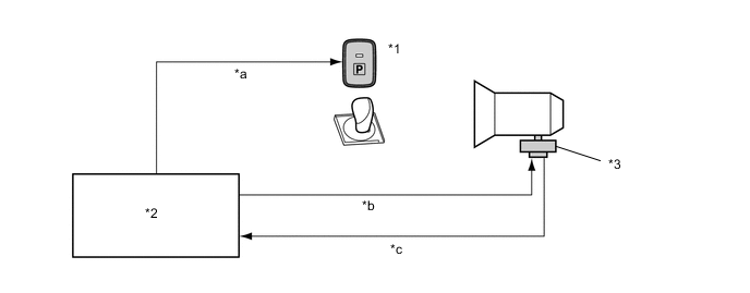
*1 P Position Switch Indicator Light *2 Transmission Control ECU Assembly *3 Shift Control Actuator Assembly - - *a ON Demand Signal *b "P Lock" Switch Control *c Rotation Angle Sensor Signal - - -
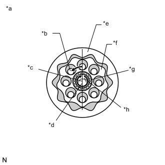
*a Cycloid Reduction Mechanism *b Output Shaft *c Center of Eccentric Adapter *d Center of Motor Input Shaft *e Internal Gear *f External Gear *g Bearing *h Eccentric Adapter The transmission control ECU assembly controls motor rotation angle based on signals from the rotation angle sensor in the shift control actuator assembly.
Tech Tips
In the cycloid reduction mechanism, the output shaft is linked to the external gear. Together, they rotate only a single tooth when the eccentric adapter, which is linked to the motor, rotates once. Driving force is increased in this way so that the parking lock mechanism can be switched even when high output is required for parking on a hill, etc.
-
The P position switch indicator light is illuminated.
-
-
Operation to switch from park (P) to a shift state other than park (P):
*1 Shift Lever *2 Hybrid Vehicle Control ECU Assembly *3 Transmission Control ECU Assembly - - *a Stop Light Switch Signal *b Shift Lever Operation Signal *c "P Lock Release" Operation Signal - -
-
When the hybrid system is started (the vehicle is ready to be driven) and the shift lever is moved to R, N, or D with the brake pedal depressed, a signal is sent to the hybrid vehicle control ECU assembly.
-
This signal is then sent from the hybrid vehicle control ECU assembly to the transmission control ECU assembly as a "P lock release" operation demand signal.
-
After receiving the signal, the transmission control ECU assembly activates the shift control actuator assembly in order to unlock the parking lock mechanism.
*1 P Position Switch Indicator Light *2 Transmission Control ECU Assembly *3 Shift Control Actuator Assembly - - *a OFF Demand Signal *b "P Lock Release" Switch Control *c Rotation Angle Sensor Signal - - -
The transmission control ECU assembly controls motor rotation angle based on signals from the rotation angle sensor in the shift control actuator assembly.
-
The P position switch indicator light is turned off.
-
-
-
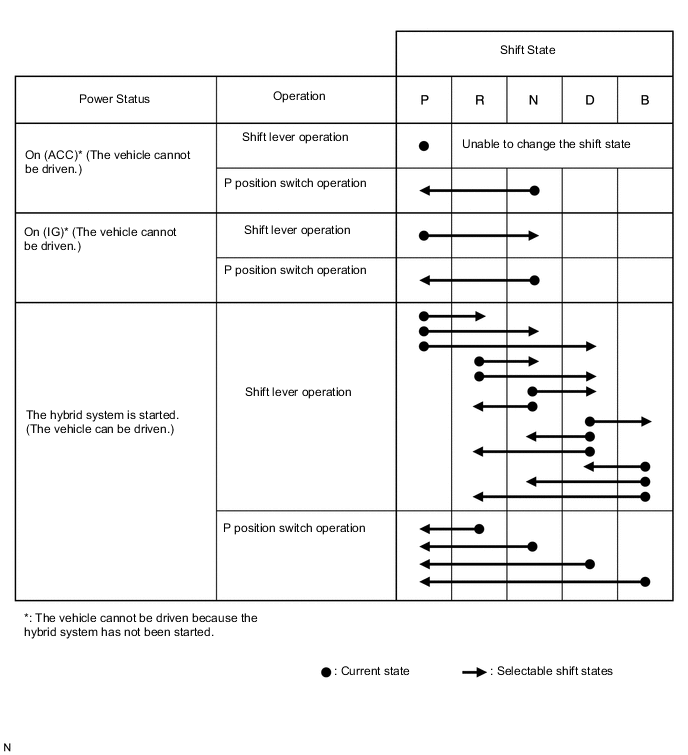
SHIFT STATE CHANGE FUNCTION
-
The electronic shift lever system comprehensively determines vehicle conditions and changes the shift state, as shown in the following chart, by cooperating with the shift control function of the hybrid system (except when the reject function described later is in operating).
-
Other than indicated in the following chart, when the power switch is turned off with the vehicle stopped, the shift state is automatically changed to park (P) and all power is turned off.
-
-
REJECT FUNCTION
-
In the electronic shift lever system, there may be a situation in which a shift state change cannot be performed for safety reasons. In such a situation, when the shift lever is moved to attempt to change the shift state, the system sounds a reject buzzer inside the meter, displays a warning message on the multi-information display and changes the shift state as shown in the following table.
Selector operation which causes reject function to operate Shift state after rejection Message displayed on multi-information display The shift lever is moved to any position with park (P) selected and the brake pedal not depressed. Remains in park (P) Shifting unavailable. Press brake pedal before shifting. The P position switch (transmission shift main switch) is pushed while driving. Changes to neutral (N) Switched to N. To engage P mode, stop car then press P switch. The shift lever is moved to R with drive (D) selected, or D with reverse (R) selected while the vehicle is moving at 11 km/h (7 mph) or more. Changes to neutral (N)
-
Switched to N. To shift to D, stop car first.
-
Switched to N. To shift to R, stop car first.
The shift lever is moved to B with a shift state other than drive (D) or park (P) selected. Changes to neutral (N)
-
Can not shift to B. Shift to D once to shift to B.
-
Switched to N. Shift to D once to shift to B.
The shift lever is moved to B with park (P) selected and the brake pedal depressed. Remains in park (P) Can not shift to B. Shift to D once to shift to B. The shift lever is moved to any position when the auxiliary battery voltage is low. Remains in park (P) 12-volt battery low. When parking, apply parking brake. Read Owner's Manual. With park (P) selected, the shift lever is moved to select another shift state when the reject function is operating. Remains in park (P) Shifting temporarily unavailable. Wait a moment. The shift lever is moved to R, D or B when the power switch is on (IG).
(If the shift lever is held in R or D for a certain amount of time, it is interpreted as the shift lever being moved to N and the shift state changes to neutral (N).)
Remains in current shift state Can not shift to D or R. Shift after hybrid system starts. -
-
-
P POSITION SWITCH INDICATOR LIGHT CONTROL
-
The P position switch indicator light comes on when park (P) is selected, goes off when a shift state other than park (P) is selected and goes off when a system malfunction occurs and an error message is displayed on the multi-information display.
P Position Switch Indicator Light DTC No. Indicator Light Suspected Cause C2300 Goes off
(An error message is displayed on the multi-information display.)
Shift count malfunction
-
Initial drive mode
-
Park lock/unlock position detection mode
-
Feedback drive mode
-
Range of movement
Continual abnormal current
C2301 Goes off
(An error message is displayed on the multi-information display.)
Shift changing time malfunction C2303 Normal
(Comes on when park (P) is selected and goes off when another shift state is selected)
P-CON relay (transaxle parking lock control relay) lockup C2304 Goes off
(An error message is displayed on the multi-information display.)
Open or short in shift control actuator assembly [parking lock motor (MUA)] signal circuit C2305 Goes off
(An error message is displayed on the multi-information display.)
Open or short in shift control actuator assembly [parking lock motor (MVA)] signal circuit C2306 Goes off
(An error message is displayed on the multi-information display.)
Open or short in shift control actuator assembly [parking lock motor (MWA)] signal circuit C2307 Goes off
(An error message is displayed on the multi-information display.)
Power source circuit malfunction C2308 Normal
(Comes on when park (P) is selected and goes off when another shift state is selected)
Transmission control ECU assembly internal error C2309 Goes off
(An error message is displayed on the multi-information display.)
Open in +B signal circuit C2310 Normal
(Comes on when park (P) is selected and goes off when another shift state is selected)
Open or short in BATT signal circuit C2311 Goes off
(An error message is displayed on the multi-information display.)
-
P control (PCON) DUTY malfunction
-
Open or short in P control (PCON) signal circuit
C2315 Normal
(Comes on when park (P) is selected and goes off when another shift state is selected)
-
Open or short in P position (PPOS) signal circuit
-
P position switch circuit malfunction
U0146 Normal
(Comes on when park (P) is selected and goes off when another shift state is selected)
CAN communication system malfunction Note
Even if the system has returned to normal, with park (P) selected, the P position switch indicator light does not return to normal without selecting a shift state other than park (P). (Normal refers to the P position switch indicator light coming on when park (P) is selected and going off when another shift state is selected.)
-
-