OIL PUMP INSTALLATION

PROCEDURE
-
INSTALL OIL PUMP ASSEMBLY
-
Install the oil pump assembly with the 3 bolts.
- Torque:
- 21 N*m { 214 kgf*cm, 16 ft.*lbf }
-
-
INSTALL NO. 2 OIL PAN SUB-ASSEMBLY
-
Remove any remaining seal packing.
Note
Be careful not to drop any oil on the contact surfaces of the cylinder block sub-assembly and No. 2 oil pan sub-assembly.
-
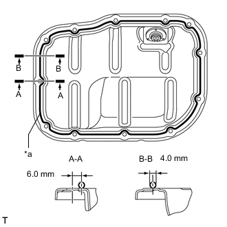
*a Seal Packing Apply a continuous bead of seal packing (diameter 4.0 mm (0.157 in.)) as shown in the illustration.
Seal packing Toyota Genuine Seal Packing Black, Three Bond 1207B or equivalent Note
-
Remove any oil from the contact surfaces.
-
Install the No. 2 oil pan sub-assembly within 3 minutes of applying seal packing.
-
Do not start the engine for at least 2 hours after installing the No. 2 oil pan sub-assembly.
-
-
Install the No. 2 oil pan sub-assembly with the 10 bolts and 2 nuts.
- Torque:
- 10 N*m { 102 kgf*cm, 7 ft.*lbf }
-
-
INSTALL OIL PAN DRAIN PLUG
-
INSTALL CRANKSHAFT TIMING GEAR KEY
-
INSTALL NO. 1 CRANKSHAFT POSITION SENSOR PLATE
-
INSTALL NO. 2 CHAIN SUB-ASSEMBLY
-
Temporarily install the crankshaft pulley bolt.
-
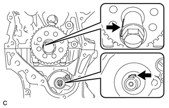
Turn the crankshaft counterclockwise to position the crankshaft timing gear key at the 9 o'clock position.
-
Turn the drive shaft so that the flat surface faces the 12 o'clock position.
-
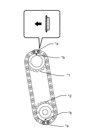
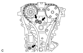
*1 Oil Pump Drive Gear *2 Oil Pump Drive Shaft Gear *a Mark Plate (Yellow) *b Timing Mark 
Engine Front Align mark plate (yellow) with the timing mark as shown in the illustration.
Tech Tips
Be sure to position the mark plates at the front of the engine.
-
Install the sprockets onto the crankshaft and oil pump shaft with the No. 2 chain sub-assembly on the gears.
-
Temporarily tighten the oil pump drive shaft gear with the nut.
-
Insert the chain damper spring into the adjusting hole, and then install the chain tensioner plate with the bolt.
- Torque:
- 10 N*m { 102 kgf*cm, 7 ft.*lbf }
-
Temporarily tighten the crankshaft pulley with the bolt.
-
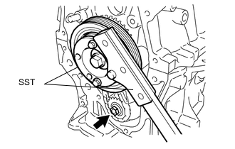
Using SST, install the oil pump drive shaft gear nut while holding the crankshaft pulley.
- SST
- 09213-58014 ( 91551-80840 )
- 09330-00021
- Torque:
- 28 N*m { 286 kgf*cm, 21 ft.*lbf }
-
Remove the crankshaft pulley and bolt.
-
-
INSTALL CRANKSHAFT TIMING SPROCKET
-
Install the crankshaft timing sprocket.
-
-
INSTALL NO. 1 CHAIN VIBRATION DAMPER
-
SET NO. 1 CYLINDER TO TDC / COMPRESSION
-
INSTALL CHAIN SUB-ASSEMBLY
-
CHECK NO. 1 CYLINDER TO TDC / COMPRESSION
-
INSTALL CHAIN TENSIONER SLIPPER
-
INSTALL NO. 2 CHAIN VIBRATION DAMPER
-
INSTALL TIMING CHAIN COVER OIL SEAL
-
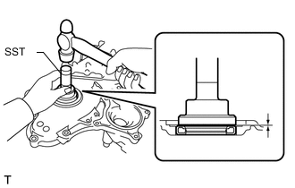
Using SST and a hammer, tap in a new timing chain cover oil seal until its surface is flush with the timing chain cover edge.
- SST
- 09223-22010
Note
-
Keep the lip free from foreign matter.
-
Do not tap in the timing chain cover oil seal at an angle.
-
Make sure that the timing chain cover oil seal edge does not stick out of the timing chain cover sub-assembly.
Tech Tips
Tap in the timing chain cover oil seal so that it is positioned within 1.0 mm (0.0394 in.) from the edge of the timing chain cover sub-assembly.
-
Apply MP grease to the lip of the timing chain cover oil seal.
-
-
INSTALL TIMING CHAIN COVER SUB-ASSEMBLY
-
Remove any remaining seal packing (FIPG).
Note
Be careful not to drop any oil on the contact surfaces of the timing chain cover sub-assembly, cylinder head sub-assembly and cylinder block sub-assembly.
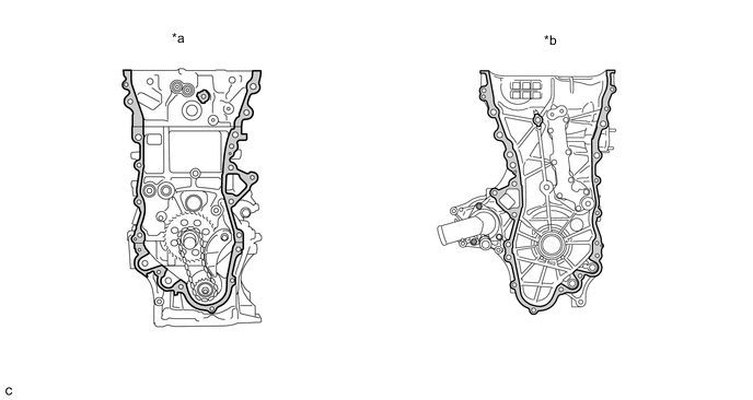
*a Engine Side *b Timing Chain Cover Side 
Surface to be cleaned - - -
Install 3 new O-rings.
-
Apply seal packing as shown in the illustration.
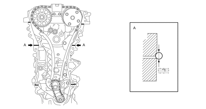
*1 5.0 mm Seal Packing Toyota Genuine Seal Packing Black, Three Bond 1207B or equivalent Seal Diameter 5.0 mm (0.197 in.) Note
-
Remove any oil from the contact surfaces.
-
Install the timing chain cover sub-assembly within 3 minutes of applying seal packing.
-
Do not start the engine for at least 2 hours after installing the timing chain cover sub-assembly.
-
-
Apply seal packing to the timing chain cover sub-assembly in a line as shown in the following illustration.
Note
-
If there is oil on the contact surfaces, wipe them with an oil-free cloth before applying seal packing.
-
Install the timing chain cover sub-assembly within 3 minutes and tighten the bolts within 15 minutes of applying seal packing.
-
Do not start the engine for at least 2 hours after installation.
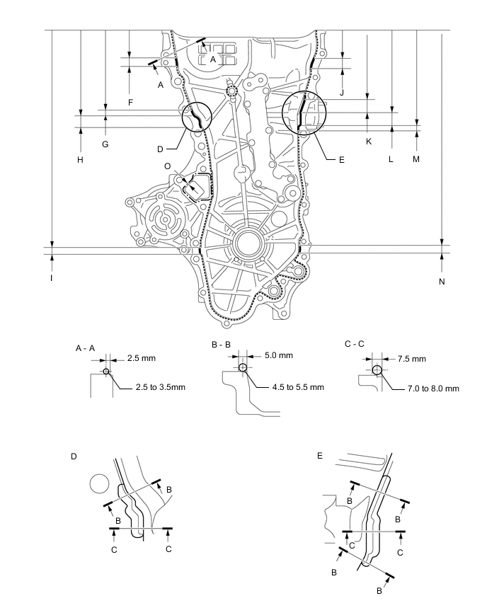
Seal Packing Item Seal Packing Dashed line Toyota Genuine Seal Packing Black, Three Bond 1207B or equivalent Continuous line Alternate long and short dashed line Toyota Genuine Seal Packing 1282B, Three Bond 1282B or equivalent Application Specification Area Seal Packing Diameter Distance from Edge of Cover to: Seal Packing Application Length Distance from Top of Cover to Top of Seal Packing Dashed line 2.5 to 3.0 mm (0.0984 to 0.118 in.) Center of seal packing
2.5 mm (0.0984 in.)
- - Continuous line 4.5 to 5.5 mm (0.177 to 0.217 in.) or 7.0 to 8.0 mm (0.276 to 0.315 in.) - - - Alternate long and short dashed line 4.0 mm (0.157 in.) Center of seal packing
3.0 mm (0.118 in.)
- - A - A 2.5 to 3.5 mm (0.0984 to 0.138 in.) Center of seal packing
2.5 mm (0.0984 in.)
- - B - B 4.5 to 5.5 mm (0.177 to 0.217 in.) Opposite edge of seal packing
5.0 mm (0.197 in.)
- - C - C 7.0 to 8.0 mm (0.276 to 0.315 in.) Opposite edge of seal packing
7.5 mm (0.295 in.)
- - F 4.5 to 5.5 mm (0.177 to 0.217 in.) - 15.5 mm (0.610 in.) 50.4 mm (1.98 in.) G 4.5 to 5.5 mm (0.177 to 0.217 in.) - 10.3 mm (0.406 in.) 143.1 mm (5.63 in.) H 7.0 to 8.0 mm (0.276 to 0.315 in.) - 19.5 mm (0.768 in.) 153.4 mm (6.04 in.) I 4.5 to 5.5 mm (0.177 to 0.217 in.) - 16.0 mm (0.630 in.) 385.8 mm (1.27 ft.) J 4.5 to 5.5 mm (0.177 to 0.217 in.) - 18.6 mm (0.732 in.) 51.4 mm (2.02 in.) K 4.5 to 5.5 mm (0.177 to 0.217 in.) - 25.3 mm (0.996 in.) 121.9 mm (4.80 in.) L 7.0 to 8.0 mm (0.276 to 0.315 in.) - 25.8 mm (1.02 in.) 147.2 mm (5.80 in.) M 4.5 to 5.5 mm (0.177 to 0.217 in.) - 5.1 mm (0.201 in.) 173.0 mm (6.81 in.) N 4.5 to 5.5 mm (0.177 to 0.217 in.) - 14.6 mm (0.575 in.) 385.8 mm (1.27 ft.) O 4.0 mm (0.157 in.) Center of seal packing
3.0 mm (0.118 in.)
- - Note
-
If there is oil on the contact surfaces, wipe them with an oil-free cloth before applying seal packing.
-
Install the timing chain cover sub-assembly within 3 minutes and tighten the bolts within 10 minutes of applying seal packing.
-
After applying seal packing to the timing chain cover sub-assembly, install the engine mounting bracket and oil filter bracket within 10 minutes.
-
Do not add engine oil for at least 2 hours after installation.
-
-
Clean the bolt and fitting hole.
-
Install the timing chain cover sub-assembly.
-
Temporarily install the engine mounting bracket RH with the 3 bolts.
Note
-
Install the engine mounting bracket RH within 10 minutes of installing the timing chain cover sub-assembly.
-
Do not start the engine for at least 2 hours after installation.
Bolt Length Item Length Bolt 80 mm (3.15 in.) -
-
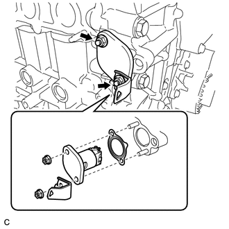
Install 2 new O-rings.
-
Temporarily tighten the oil filter bracket with the 4 bolts.
Note
-
Install the oil filter bracket within 10 minutes of installing the timing chain cover sub-assembly.
-
Do not start the engine for at least 2 hours after installation.
Bolt Length Item Length Bolt 35 mm (1.38 in.) -
-
Install the timing chain cover sub-assembly with the 25 bolts and seal washer as shown in the illustration.
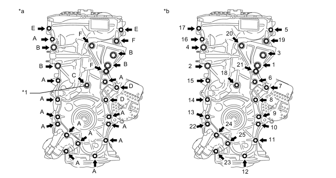
*1 Seal Washer - - *a Torque *b Bolt Tightening Order - Torque:
- Bolt A, E
- 26 N*m { 265 kgf*cm, 19 ft.*lbf }
- Bolt B, F
- 51 N*m { 520 kgf*cm, 38 ft.*lbf }
- Bolt C, D
- 10 N*m { 102 kgf*cm, 7 ft.*lbf }
Note
-
Apply adhesive 1324 to the threads of the bolt (F).
-
If there is oil on the contact surfaces, wipe them with an oil-free cloth before applying seal packing.
-
Install the timing chain cover sub-assembly within 3 minutes and tighten the bolts within 15 minutes of applying the seal packing.
-
Do not add engine oil for at least 2 hours after installing the timing chain cover sub-assembly.
-
Do not start the engine for at least 2 hours after installing the timing chain cover sub-assembly.
Bolt Length Item Length Bolt A, F 35 mm (1.38 in.) Bolt B 55 mm (2.16 in.) Bolt C 80 mm (3.15 in.) Bolt D 40 mm (1.57 in.) Bolt E 55 mm (2.16 in.) -
Using an 8 mm socket wrench, install the stud bolt to the engine mounting bracket RH.
- Torque:
- 10 N*m { 102 kgf*cm, 7 ft.*lbf }
-
-
INSTALL CRANKSHAFT PULLEY
-
INSTALL NO. 1 CHAIN TENSIONER ASSEMBLY
-
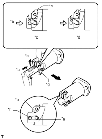
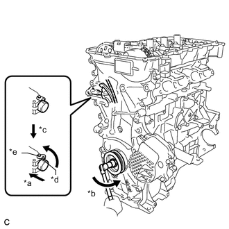
*a Push *b Raise *c Correct *d Incorrect *e Cam *f Pin *g Hook Release the cam, and then fully push in the plunger and engage the hook to the pin so that the plunger is in the position shown in the illustration.
Note
Make sure that the cam engages the first tooth of the plunger to allow the hook to pass over the pin.
-
Install a new gasket, the bracket and No. 1 chain tensioner assembly with the 2 nuts.
- Torque:
- 12 N*m { 122 kgf*cm, 9 ft.*lbf }
Note
If the hook releases the plunger while the No. 1 chain tensioner assembly is being installed, engage the hook again.
-
*a Push *b Turn *c Release *d Pin *e Hook Rotate the crankshaft counterclockwise slightly and check that the hook is released.
-
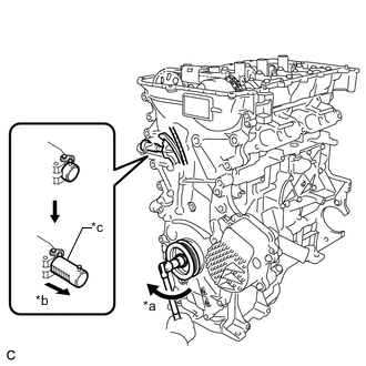
*a Turn *b Plunger is extended *c Plunger Turn the crankshaft clockwise and check that the plunger is extended.
-
-
INSTALL SPARK PLUG TUBE GASKET
-
INSTALL CYLINDER HEAD COVER GASKET
-
INSTALL CYLINDER HEAD COVER SUB-ASSEMBLY
-
INSTALL IGNITION COIL ASSEMBLY
-
INSTALL NO. 3 WATER BY-PASS HOSE
-
INSTALL FUEL VAPOR FEED PIPE
-
INSTALL INTAKE MANIFOLD
-
INSTALL EGR VALVE WITH COOLER ASSEMBLY
-
INSTALL EGR PIPE ASSEMBLY
-
INSTALL THROTTLE BODY ASSEMBLY
-
INSTALL ENGINE HANGERS
-
REMOVE ENGINE FROM ENGINE STAND
-
INSTALL ENGINE ASSEMBLY WITH TRANSAXLE