REAR UPPER ARM INSTALLATION
CAUTION / NOTICE / HINT
Tech Tips
-
Use the same procedure for the RH side and LH side.
-
The procedure listed below is for the LH side.
PROCEDURE
-
TEMPORARILY INSTALL REAR UPPER CONTROL ARM ASSEMBLY
-

Using a brass bar and a hammer, push out the bushing until it is positioned as shown in the illustration.
Note
Do not damage the bushing.
Tech Tips
Pushing out the bushing makes it easier to install the rear upper control arm assembly.
-
Using a jack and wooden block, keep the rear No. 2 suspension arm assembly level.
CAUTION:
Do not jack up the rear No. 2 suspension arm assembly too high as the vehicle may fall.
Note
-
When jacking up the rear No. 2 suspension arm assembly, be sure to jack it up slowly.
-
Make sure to perform this operation with the vehicle kept as low as possible.
-
-
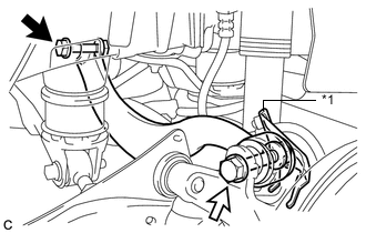
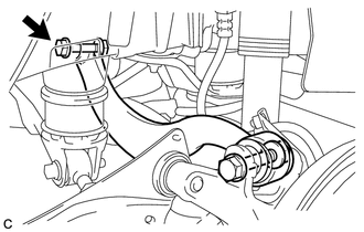
*1 No. 2 Flexible Hose Bracket 
Bolt (A) 
Bolt (B) Temporarily install the rear upper control arm assembly to the rear suspension member sub-assembly with the bolt (A) and nut.
Note
-
Because the nut has its own stopper, do not turn the nut. Tighten the bolt with the nut secured.
-
Insert the bolt with the threaded end facing the rear of the vehicle.
-
-
Fully install the rear upper control arm assembly and No. 2 flexible hose bracket to the rear axle assembly with the bolt (B) and nut.
- Torque:
- 90 N*m { 918 kgf*cm, 66 ft.*lbf }
Note
-
Because the nut has its own stopper, do not turn the nut. Tighten the bolt with the nut secured.
-
Insert the bolt with the threaded end facing the rear of the vehicle.
-
-
STABILIZE SUSPENSION
-
FULLY TIGHTEN REAR UPPER CONTROL ARM ASSEMBLY
-
Fully tighten the bolt.
- Torque:
- 90 N*m { 918 kgf*cm, 66 ft.*lbf }
Note
-
Because the nut has its own stopper, do not turn the nut. Tighten the bolt with the nut secured.
-
Make sure that the rear No. 2 suspension arm assembly remains level when fully tightening the bolt.
-
-
INSTALL REAR FLOOR SIDE MEMBER COVER LH (for LH Side)
-
INSTALL REAR FLOOR SIDE MEMBER COVER RH (for RH Side)
-
INSTALL REAR SUSPENSION ARM COVER
-
INSTALL REAR WHEEL
- Torque:
- 103 N*m { 1050 kgf*cm, 76 ft.*lbf }
-
INSPECT AND ADJUST REAR WHEEL ALIGNMENT