ПЕРЕКЛЮЧАТЕЛЬ РЕЖИМА ПРОВЕРКА
PROCEDURE
-
INSPECT Es MODE SWITCH (COMBINATION SWITCH ASSEMBLY)
-
Make sure that there is no looseness in the locking part and the connecting part of the connector.
-
Disconnect the Es mode switch (combination switch assembly) connector.
-
Check both the connector case and the terminal for deformation and corrosion.
OK No deformation or corrosion. -
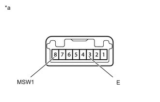
*a Component without harness connected
(Es mode Switch (Combination Switch Assembly))
Measure the resistance according to the value(s) in the table below.
Standard Resistance Tester Connection Switch Condition Specified Condition 3 (E) - 8 (MSW1) Switch pushed in Below 50 Ω Switch not pushed in 10 kΩ or higher If the result is not as specified, replace the Es mode switch (combination switch assembly).
-
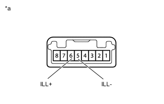
*a Component without harness connected
(Es mode Switch (Combination Switch Assembly))
Apply battery voltage between the terminals of the switch and check the illumination condition of the Es mode switch (combination switch assembly).
Standard Measurement Condition Specified Condition Battery positive (+) → 6 (ILL+)
Battery negative (-) → 5 (ILL-)
Illuminates If the result is not as specified, replace the Es mode switch (combination switch assembly).
-