ДАТЧИК ВЫБОРА ПЕРЕДАЧ ПРОВЕРКА
PROCEDURE
-
INSPECT SELECT STROKE SENSOR
-
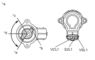
*a Main *b Select Stroke Sensor Arm *c 55° *d 0° *e -55° Measure the voltage between the terminals of the select stroke sensor connector (main).
-
Prepare 3 dry cell batteries (1.5 V) and 2 leads for connecting the batteries and the sensor.
-
Connect the batteries in series.
-
Connect the positive battery terminal to sensor terminal 4 (VCL1), and the negative battery terminal to sensor terminal 5 (E2L1).
-
Measure the voltage according to the value(s) in the table below.
Standard Voltage (combined dry cell battery voltage of 4.5 V) Tester Connection Condition
(Sensor Angle)
Specified Condition 6 (VSL1) - 5 (E2L1) 55° 3.6 to 4.5 V 0° 1.8 to 2.7 V -55° 0.27 to 0.63 V Reference Voltage (combined dry cell battery voltage of 5.0 +/- 0.3 V) Tester Connection Sensor Angle Specified Condition 6 (VSL1) - 5 (E2L1) 55° 4.0 to 5.0 V 0° 2.0 to 3.0 V -55° 0.3 to 0.7 V If the voltage is not as specified, replace the select stroke sensor.
-
-
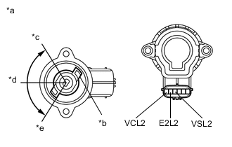
*a Sub *b Select Stroke Sensor Arm *c 55° *d 0° *e -55° Measure the voltage between the terminals of the select stroke sensor connector (sub).
-
Connect the positive battery terminal to sensor terminal 1 (VCL2) , and the negative battery terminal to sensor terminal 2 (E2L2).
-
Measure the voltage according to the value(s) in the table below.
Standard Voltage (combined dry cell battery voltage of 4.5 V) Tester Connection Condition
(Sensor Angle)
Specified Condition 3 (VSL2) - 2 (E2L2) 55° 3.6 to 4.5 V 0° 1.8 to 2.7 V -55° 0.27 to 0.63 V Reference Voltage (combined dry cell battery voltage of 5.0 +/- 0.3 V) Tester Connection Sensor Angle Specified Condition 3 (VSL2) - 2 (E2L2) 55° 4.0 to 5.0 V 0° 2.0 to 3.0 V -55° 0.3 to 0.7 V Note
-
Do not apply more than 6 V.
-
Do not use a sensor which has been dropped.
If the voltage is not as specified, replace the select stroke sensor.
-
-
-