ПЕРВИЧНЫЙ ВАЛ ПРОВЕРКА

PROCEDURE
-
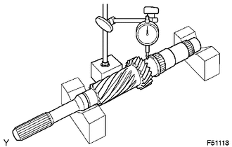
INSPECT INPUT SHAFT
-
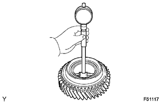
Using a dial indicator and 2 V-blocks, measure the shaft runout.
Maximum runout 0.03 mm (0.00118 in.) If the runout is more than the maximum, replace the input shaft.
-
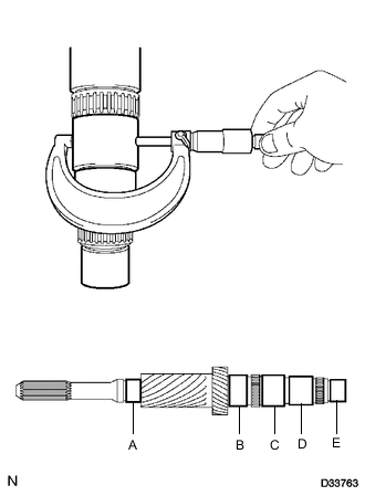
Using a micrometer, measure the journal diameter of each input shaft journal at the specified positions.
Standard Journal Diameter Item Specified Condition Journal A 34.002 to 34.015 mm (1.3387 to 1.3392 in.) Journal B 44.989 to 45.000 mm (1.7713 to 1.7716 in.) Journal C 44.985 to 45.000 mm (1.7711 to 1.7716 in.) Journal D 41.985 to 42.000 mm (1.6530 to 1.6535 in.) Journal E 32.967 to 32.974 mm (1.2979 to 1.2982 in.) Minimum Diameter Item Specified Condition Journal A 34.002 mm (1.3387 in.) Journal B 44.989 mm (1.7713 in.) Journal C 44.985 mm (1.7711 in.) Journal D 41.985 mm (1.6530 in.) Journal E 32.967 mm (1.2979 in.) If the journal diameter is less than the minimum, replace the input shaft.
-
-
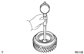
INSPECT 6TH GEAR SUB-ASSEMBLY
-
Using a cylinder gauge, measure the inside diameter of the 6th gear.
Standard inside diameter 51.015 to 51.040 mm (2.0085 to 2.0095 in.) Maximum inside diameter 51.040 mm (2.0095 in.) If the inside diameter is more than the maximum, replace the 6th gear.
-
-
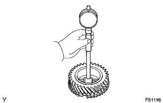
INSPECT 3RD GEAR
-
Using a cylinder gauge, measure the inside diameter of the 3rd gear.
Standard inside diameter 51.015 to 51.040 mm (2.0085 to 2.0095 in.) Maximum inside diameter 51.040 mm (2.0095 in.) If the inside diameter is more than the maximum, replace the 3rd gear.
-
-
INSPECT 4TH GEAR
-
Using a cylinder gauge, measure the inside diameter of the 4th gear.
Standard inside diameter 51.015 to 51.028 mm (2.0085 to 2.0089 in.) Maximum inside diameter 51.028 mm (2.0089 in.) If the inside diameter is more than the maximum, replace the 4th gear.
-
-
INSPECT NO. 2 TRANSMISSION HUB SLEEVE
-
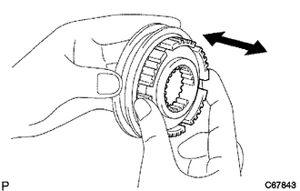
Check the sliding condition between the No. 2 transmission hub and No. 2 transmission hub sleeve.
-
Check that the splines of the No. 2 transmission hub sleeve are not worn.
-
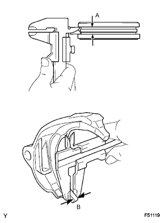
Using a vernier caliper, measure the width of the No. 2 transmission hub sleeve groove (A) and the thickness of the claw part of the No. 2 or No. 3 gear shift forks (B), and calculate the clearance.
Standard clearance A - B: 0.28 to 0.84 mm (0.0111 to 0.0331 in.) for No. 2 gear shift fork 0.28 to 0.66 mm (0.0111 to 0.0259 in.) for No. 3 gear shift fork If the clearance is outside the specification, replace the No. 2 transmission hub sleeve and gear shift fork.
-
-
INSPECT NO. 3 SYNCHRONIZER RING (for 6th Gear)
-
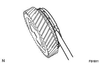
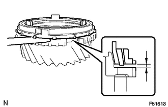
Using a feeler gauge, measure the clearance between the synchronizer ring and 6th gear.
Standard clearance 0.70 to 1.50 mm (0.0276 to 0.0591 in.) Minimum clearance 0.70 mm (0.0276 in.) If the clearance is less than the minimum, replace the synchronizer ring.
-
Coat the 6th gear cone with gear oil.
-
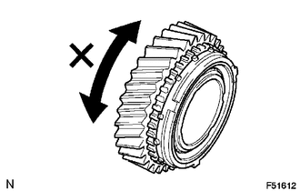
Check the braking effect of the synchronizer ring.
-
Turn the synchronizer ring in both directions while pushing it against the 6th gear cone. Check that the ring locks in both directions.
-
If No. 3 synchronizer ring turns, replace it.
-
-
-
-
INSPECT NO. 2 SYNCHRONIZER RING SET (for 3rd Gear)
-
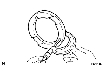
Using a feeler gauge, measure the clearance between the synchronizer ring and 3rd gear.
Standard clearance Inner 1.20 to 2.20 mm (0.0472 to 0.0866 in.) Middle 0.30 to 2.10 mm (0.0119 to 0.0826 in.) Outer 0.80 to 1.80 mm (0.0315 to 0.0709 in.) Minimum clearance Inner 1.20 mm (0.0472 in.) Middle 0.30 mm (0.0119 in.) Outer 0.80 mm (0.0315 in.) If the clearance is less than the minimum, replace the synchronizer ring.
-
Coat the 3rd gear cone with gear oil.
-
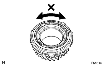
Check the braking effect of the synchronizer ring.
-
Turn the synchronizer ring in both directions while pushing it against the 3rd gear cone. Check that the ring locks in both directions.
-
If No. 2 synchronizer ring set turns, replace it.
-
-
-
-
INSPECT NO. 3 SYNCHRONIZER RING (for 4th Gear)
-
Using a feeler gauge, measure the clearance between the synchronizer ring and 4th gear.
Standard clearance 0.70 to 1.50 mm (0.0276 to 0.0591 in.) Minimum clearance 0.70 mm (0.0276 in.) If the clearance is less than the minimum, replace the synchronizer ring.
-
Coat the 4th gear cone with gear oil.
-
Check the braking effect of the synchronizer ring.
-
Turn the synchronizer ring in both directions while pushing it against the 4th gear cone. Check that the ring locks in both directions.
-
If No. 3 synchronizer ring turns, replace it.
-
-
-
-
INSPECT 3RD GEAR THRUST WASHER
-
Using a micrometer, measure the thrust washer thickness.
Standard thickness 7.12 to 7.18 mm (0.2803 to 0.2827 in.) Minimum thickness 7.12 mm (0.2803 in.) If the thickness is less than the minimum, replace the thrust washer.
-