ВЫХОДНОЙ ВАЛ ПРОВЕРКА

PROCEDURE
-
INSPECT OUTPUT SHAFT
-
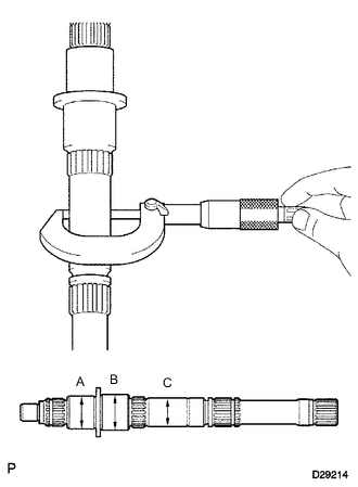
Using a micrometer, measure the journal diameter of the output shaft journal surface.
Standard Journal diameter Item Specified Condition Journal A 34.984 to 35.000 mm (1.3774 to 1.3779 in.) Journal B 37.984 to 38.000 mm (1.4955 to 1.4960 in.) Journal C 30.384 to 30.400 mm (1.1963 to 1.1968 in.)
-
If the result is not as specified, replace the output shaft.
-
-
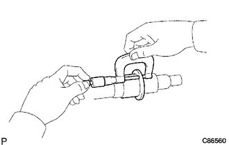
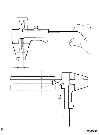
Using a micrometer, measure the flange thickness.
Standard thickness 4.80 to 5.20 mm (0.189 to 0.204 in.) Minimum thickness 4.80 mm (0.189 in.)
-
If the thickness is less than the minimum, replace the output shaft.
-
-
-
INSPECT 1ST GEAR BEARING INNER RACE
-
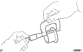
Using a micrometer, measure the inner race thickness.
Standard thickness 3.995 to 4.195 mm (0.158 to 0.165 in.) Minimum thickness 3.995 mm (0.158 in.)
-
If the thickness is less than the minimum, replace the 1st gear bearing inner race.
-
-
Using a micrometer, measure the outside diameter of the inner race.
Standard outside diameter 38.985 to 39.000 mm (1.5349 to 1.5354 in.) Minimum outside diameter 38.985 mm (1.5349 in.)
-
If the outside diameter is less than the minimum, replace the 1st gear bearing inner race.
-
-
-
INSPECT NO. 1 SYNCHRONIZER RING (for 1st Gear)
-
Coat the 1st gear cone with gear oil.
-
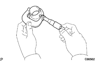
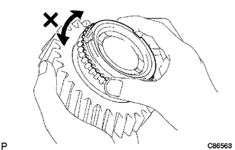
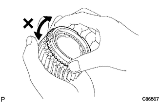
Check the braking effect of the No. 1 synchronizer ring.
-
Install the ring to the shaft cone.
-
Apply pressure to the ring and attempt to turn it in both directions. Check that the ring locks.
-
If the braking effect is insufficient, apply a small amount of fine lapping compound between the No. 1 synchronizer ring and the 1st gear cone. Lightly rub the No. 1 synchronizer ring and the 1st gear cone together. Check the braking effect of the No. 2 synchronizer ring again.
Note
Make sure the fine lapping compound is completely washed off after rubbing.
-
-
-
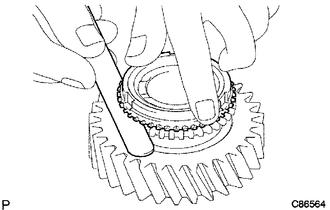
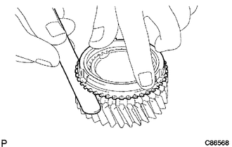
Using a feeler gauge, measure the clearance between the No. 1 synchronizer ring back and 1st gear spline end.
Standard clearance 1.00 to 2.00 mm (0.0394 to 0.0787 in.)
-
If the result is not as specified, replace the No. 1 synchronizer ring and apply a small amount of fine lapping compound to the 1st gear cone.
Note
Make sure the fine lapping compound is completely washed off after rubbing.
-
-
-
INSPECT NO. 1 SYNCHRONIZER RING (for 2nd Gear)
-
Coat the 2nd gear cone with gear oil.
-
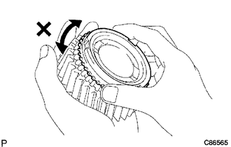
Check the braking effect of the No. 1 synchronizer ring.
-
Install the ring to the shaft cone.
-
Apply pressure to the ring and attempt to turn it in both directions. Check that the ring locks.
-
If the braking effect is insufficient, apply a small amount of fine lapping compound between the No. 1 synchronizer ring and the 2nd gear cone. Lightly rub the No. 1 synchronizer ring and the 2nd gear cone together. Check the braking effect of the No. 2 synchronizer ring again.
Note
Make sure the fine lapping compound is completely washed off after rubbing.
-
-
-
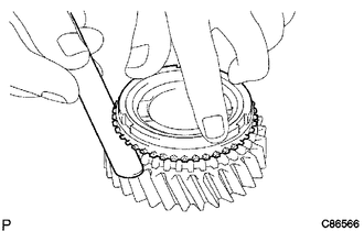
Using a feeler gauge, measure the clearance between the No. 1 synchronizer ring back and 2nd gear spline end.
Standard clearance 1.00 to 2.00 mm (0.0394 to 0.0787 in.)
-
If the result is not as specified, replace the No. 1 synchronizer ring, and apply a small amount of fine lapping compound to the 2nd gear cone.
Note
Make sure the fine lapping compound is completely washed off after rubbing.
-
-
-
INSPECT NO. 2 SYNCHRONIZER RING
-
Coat the 3rd gear cone with gear oil.
-
Check the braking effect of the No. 2 synchronizer ring.
-
Install the ring to the shaft cone.
-
Apply pressure to the ring and attempt to turn it in both directions. Check that the ring locks.
-
If the braking effect is insufficient, apply a small amount of fine lapping compound between the No. 2 synchronizer ring and the 3rd gear cone. Lightly rub the No. 2 synchronizer ring and the 3rd gear cone together. Check the braking effect of the No. 2 synchronizer ring again.
Note
Make sure the fine lapping compound is completely washed off after rubbing.
-
-
-
Using a feeler gauge, measure the clearance between the No. 2 synchronizer ring back and 3rd gear spline end.
Standard clearance 1.0 to 2.0 mm (0.0394 to 0.0787 in.)
-
If the result is not as specified, replace the No. 2 synchronizer ring and apply a small amount of fine lapping compound to the 3rd gear cone.
Note
Make sure the fine lapping compound is completely washed off after rubbing.
-
-
-
INSPECT REVERSE GEAR
-
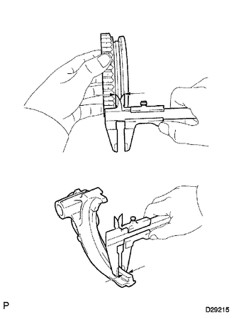
Using a vernier caliper, measure the clearance between the reverse gear and No. 1 gear shift fork.
Standard clearance 0.15 to 0.35 mm (0.00591 to 0.0137 in.) Maximum clearance 0.35 mm (0.0137 in.)
-
If the clearance is more than the maximum, replace the No. 1 gear shift fork and reverse gear.
-
-
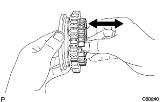
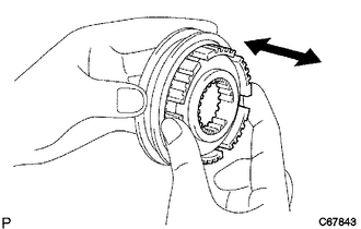
Check that the No. 1 transmission clutch hub and reverse gear slide smoothly.
-
Check that the splines of the reverse gear are not worn down.
-
-
INSPECT NO. 2 TRANSMISSION HUB SLEEVE
-
Using a vernier caliper, measure the No. 2 hub sleeve and No. 2 gear shift fork as shown in the illustration.
Standard clearance 0.15 to 0.35 mm (0.00591 to 0.0137 in.)
-
If the result is not as specified, replace the transmission hub sleeve and the No. 2 gear shift fork.
-
-
Check the sliding condition between the No. 2 hub sleeve and No. 2 clutch hub.
-
Check that the splines of the No. 2 transmission hub sleeve are not worn down.
-
-
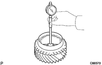
INSPECT 1ST GEAR
-
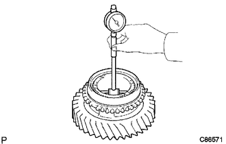
Using a cylinder gauge, measure the inside diameter of the 1st gear.
Standard inside diameter 44.015 to 44.040 mm (1.7329 to 1.7338 in.) Maximum inside diameter 44.040 mm (1.7338 in.)
-
If the inside diameter is more than the maximum, replace the 1st gear.
-
-
-
INSPECT 2ND GEAR
-
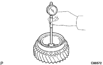
Using a cylinder gauge, measure the inside diameter of the 2nd gear.
Standard inside diameter 44.015 to 44.040 mm (1.7329 to 1.7338 in.) Maximum inside diameter 44.040 mm (1.7338 in.)
-
If the inside diameter is more than the maximum, replace the 2nd gear.
-
-
-
INSPECT 3RD GEAR
-
Using a cylinder gauge, measure the inside diameter of the 3rd gear.
Standard inside diameter 44.015 to 44.040 mm (1.7329 to 1.7338 in.) Maximum inside diameter 44.040 mm (1.7338 in.)
-
If the inside diameter is more than the maximum, replace the 3rd gear.
-
-