МЕХАНИЧЕСКАЯ ТРАНСМИССИЯ В СБОРЕ УСТАНОВКА
PROCEDURE
-
INSTALL TRANSFER ASSEMBLY
-
INSTALL MANUAL TRANSMISSION UNIT ASSEMBLY
-
Align the input shaft with the clutch disc and install the transmission to the engine.
-
Install the 4 bolts.
- Torque:
- 72 N*m { 730 kgf*cm, 52 ft.*lbf }
-
-
INSTALL STIFFENER PLATE LH
-
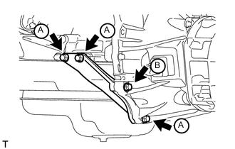
Install the stiffener plate with the 4 bolts.
- Torque:
- for bolt A
- 37 N*m { 380 kgf*cm, 27 ft.*lbf }
- for bolt B
- 69 N*m { 701 kgf*cm, 50 ft.*lbf }
-
-
INSTALL STIFFENER PLATE RH
-
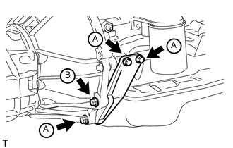
Install the stiffener plate with the 4 bolts.
- Torque:
- for bolt A
- 37 N*m { 380 kgf*cm, 27 ft.*lbf }
- for bolt B
- 69 N*m { 701 kgf*cm, 50 ft.*lbf }
-
-
INSTALL REAR NO. 1 ENGINE MOUNTING INSULATOR
-
Install the mounting insulator with the 4 bolts.
- Torque:
- 73 N*m { 739 kgf*cm, 54 ft.*lbf }
-
-
INSTALL NO. 3 FRAME CROSSMEMBER SUB-ASSEMBLY
-
Install the frame crossmember with the 4 bolts and 4 nuts.
- Torque:
- 72 N*m { 734 kgf*cm, 53 ft.*lbf }
-
Install the 4 bolts to the rear No. 1 engine mounting insulator.
- Torque:
- 30 N*m { 306 kgf*cm, 22 ft.*lbf }
-
-
INSTALL FRONT SUSPENSION MEMBER BRACKET LH
-
Install the member bracket with the 4 bolts.
- Torque:
- 33 N*m { 337 kgf*cm, 24 ft.*lbf }
-
-
INSTALL FRONT SUSPENSION MEMBER BRACKET RH
-
Install the member bracket with the 4 bolts.
- Torque:
- 33 N*m { 337 kgf*cm, 24 ft.*lbf }
-
-
INSTALL STARTER ASSEMBLY
-
Install the starter Click here.
-
-
CONNECT CLUTCH RELEASE CYLINDER ASSEMBLY
-
Connect the release cylinder with the 2 bolts.
- Torque:
- 12 N*m { 120 kgf*cm, 9 ft.*lbf }
-
-
INSTALL TRANSFER AND MANUAL TRANSMISSION BREATHER HOSE SUB-ASSEMBLY
-
Install the 3 breather hoses to the shift lever retainer and transfer adapter and attach the clamp.
-
-
CONNECT WIRE HARNESS
-
Connect the 2 connectors and attach the 4 clamps.
-
-
INSTALL PROPELLER SHAFT ASSEMBLY
-
Install the propeller shaft Click here.
-
-
INSTALL FRONT PROPELLER SHAFT ASSEMBLY
-
Install the front propeller shaft Click here.
-
-
INSTALL FRONT EXHAUST PIPE ASSEMBLY
-
Install the front exhaust pipe Click here.
-
-
ADD MANUAL TRANSMISSION OIL
-
INSTALL TRANSFER CASE LOWER PROTECTOR
-
Install the transfer case lower protector with the 4 bolts.
- Torque:
- 18 N*m { 184 kgf*cm, 13 ft.*lbf }
-
-
INSTALL SHIFT LEVER ASSEMBLY
-
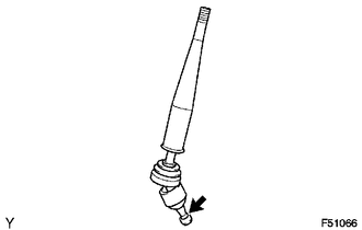
Apply MP grease to the tip of the shift lever assembly.
Text in Illustration 
MP Grease -
Cover the shift lever cap with a cloth.
-
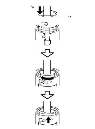
Text in Illustration *1 Shift Lever Cap *a Press down *b Clockwise *c Lock While pressing down on the shift lever cap, turn it clockwise to install the shift lever assembly.
-
-
INSTALL NO. 1 SHIFT AND SELECT LEVER BOOT
-
Install the boot with the 4 screws and 2 clips.
-
-
INSTALL CENTER FLOOR CARPET ASSEMBLY (for Bench Seat Type)
-
Install the center floor carpet assembly with the 4 bolts.
- Torque:
- 7.0 N*m { 71 kgf*cm, 61 in.*lbf }
-
-
INSTALL FRONT SEAT ASSEMBLY (for Bench Seat Type)
-
INSTALL CONSOLE BOX (for Bench Seat Type)
-
INSTALL CONSOLE PANEL SUB-ASSEMBLY (for Separate Type)
for Manual Transmission: Click here
w/ Refrigerated Cool Box: Click here
-
INSTALL SHIFT LEVER KNOB SUB-ASSEMBLY
-
CONNECT CABLE TO NEGATIVE BATTERY TERMINAL
Note
When disconnecting the cable, some systems need to be initialized after the cable is reconnected Click here.