БЛОК СЦЕПЛЕНИЯ (для моделей с 5L-E) ПРОВЕРКА

PROCEDURE
-
INSPECT CLUTCH DISC ASSEMBLY
-
Using a vernier caliper, measure the rivet head depth.
Minimum rivet head depth 0.3 mm (0.0118 in.) If the depth is less than the minimum, replace the clutch disc assembly.
-
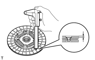
Using a dial indicator, check the disc runout.
Maximum runout 0.8 mm (0.0315 in.) Note
Be sure to measure on the correct side of the clutch disc.
If the runout is more than the maximum, replace the clutch disc assembly.
-
-
INSPECT CLUTCH COVER ASSEMBLY
-
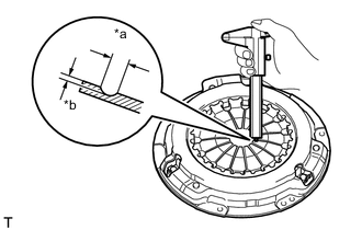
Text in Illustration *a Width *b Depth Using a vernier caliper, measure the depth and width of the worn areas of the diaphragm spring.
Maximum Wear Item Specified Condition Width 6.0 mm (0.236 in.) Depth 0.35 mm (0.0137 in.) If the depth or width is more than the maximum, replace the clutch cover assembly.
-
-
INSPECT FLYWHEEL SUB-ASSEMBLY
-
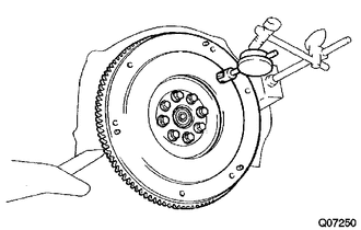
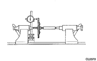
Using a dial indicator, measure the flywheel runout.
Maximum runout 0.1 mm (0.00393 in.) If the runout is more than the maximum, replace the flywheel sub-assembly.
-
-
INSPECT CLUTCH RELEASE BEARING ASSEMBLY
-
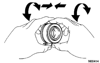
Check that the bearing turns smoothly by hand by applying force in the axial direction.
If the bearing sticks or has a considerable amount of resistance, replace the release bearing.
Tech Tips
The bearing is permanently lubricated and requires no cleaning or lubrication.
-
-
INSPECT INPUT SHAFT FRONT BEARING
-
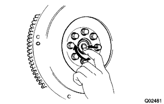
Check that the bearing turns smoothly by hand by applying rotational force.
If the bearing sticks or has a considerable amount of resistance, replace the input shaft front bearing.
Tech Tips
The bearing is permanently lubricated and requires no cleaning or lubrication.
-
-
REPLACE INPUT SHAFT FRONT BEARING
-
Remove any 2 diametrically opposite bolts.
-
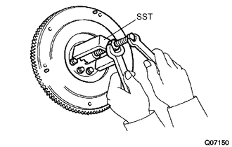
Using SST, remove the input shaft bearing.
- SST
- 09303-35011
-
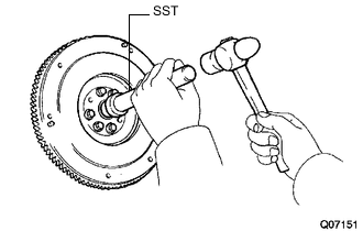
Using SST and a hammer, tap in a new bearing.
- SST
- 09304-12012
Tech Tips
After installing the bearing to the hub, make sure that it rotates smoothly.
-
Apply adhesive to 2 or 3 threads of the bolts.
Adhesive Toyota Genuine Adhesive 1324, Three Bond 1324 or equivalent -
Install the 2 bolts.
- Torque:
- 123 N*m { 1249 kgf*cm, 90 ft.*lbf }
-