ВЫПУСКНОЙ КОЛЛЕКТОР УСТАНОВКА
PROCEDURE
-
INSTALL EXHAUST MANIFOLD
-
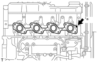
Text in Illustration *a Front Mark Install a new gasket to the cylinder head.
Tech Tips
Be sure to install a new gasket in the correct direction as shown in the illustration.
-
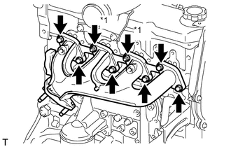
Text in Illustration *1 Nut Install the exhaust manifold with the 6 bolts and 2 new nuts. Uniformly tighten the bolts and nuts in several steps.
- Torque:
- 52 N*m { 530 kgf*cm, 38 ft.*lbf }
-
-
INSTALL NO. 1 EXHAUST MANIFOLD HEAT INSULATOR
-
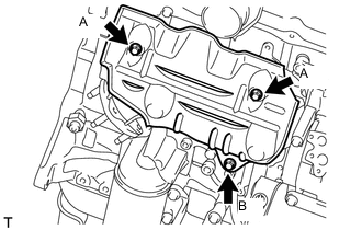
Install the insulator with the 3 bolts.
- Torque:
- for bolt A
- 18 N*m { 185 kgf*cm, 13 ft.*lbf }
- for bolt B
- 19 N*m { 195 kgf*cm, 14 ft.*lbf }
-
-
INSTALL ENGINE OIL LEVEL DIPSTICK GUIDE
-
Apply clean engine oil to a new O-ring.
-
Install the O-ring to the guide.
-
Install the guide with the 2 bolts.
- Torque:
- 18 N*m { 185 kgf*cm, 13 ft.*lbf }
-
-
INSTALL ENGINE OIL LEVEL DIPSTICK
-
Install the oil level dipstick to the guide.
-
-
INSTALL FRONT EXHAUST PIPE ASSEMBLY
-
INSTALL INTAKE PIPE
-
INSTALL RESONATOR WITH AIR CLEANER CAP SUB-ASSEMBLY
-
Insert the hinge part of the air cleaner cap and hose into the air cleaner case, and then attach the 4 hook clamps.
-
Connect the air cleaner cap sub-assembly with the clamp.
- Torque:
- 5.0 N*m { 51 kgf*cm, 44 in.*lbf }
-
Attach the wire harness clamp.
-
Connect the 2 clamps and connector.
-
-
INSPECT FOR EXHAUST GAS LEAK
-
INSTALL FRONT NO. 1 FENDER APRON TO FRAME SEAL RH
-
INSTALL FRONT FENDER APRON SEAL RH