БЛОК ЦИЛИНДРОВ ПОВТОРНАЯ СБОРКА

PROCEDURE
-
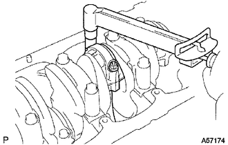
INSTALL STUD BOLT
Note
If a stud bolt is deformed or the threads are damaged, replace it.
-
Install the stud bolts as shown in the illustration.
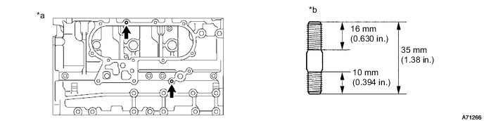
Text in Illustration *a Right Side *b Thread diameter: 8 mm - Torque:
- 15 N*m { 148 kgf*cm, 11 ft.*lbf }
-
-
INSTALL NO. 1 TAPER SCREW PLUG
-
Apply adhesive to 2 or 3 threads of the screw plug.
Adhesive Toyota Genuine Adhesive 1324, Three Bond 1324 or equivalent -
Install the screw plug.
- Torque:
- 20 N*m { 199 kgf*cm, 14 ft.*lbf }
-
-
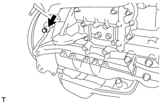
INSTALL CYLINDER BLOCK WATER DRAIN COCK SUB-ASSEMBLY
-
Apply adhesive to 2 or 3 threads of the water drain cock.
Adhesive Toyota Genuine Adhesive 1324, Three Bond 1324 or equivalent Text in Illustration *1 Adhesive -
Text in Illustration *1 Port *a Downward Install the water drain cock.
- Torque:
- 57 N*m { 581 kgf*cm, 42 ft.*lbf }
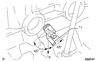
Tech Tips
-
After tightening the drain cock to the specified torque, rotate the drain union clockwise until its drain port is facing downward.
-
The drain port may be set within 45° of either side of the prescribed position.
-
-
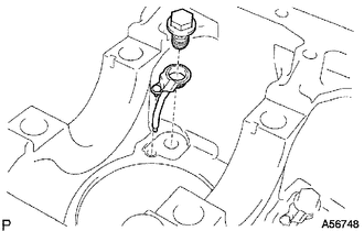
INSTALL CYLINDER BLOCK OIL ORIFICE
-
Using a 6 mm hexagon socket wrench, install the oil orifice.
- Torque:
- 11 N*m { 110 kgf*cm, 8 ft.*lbf }
-
-
INSTALL NO. 1 OIL NOZZLE SUB-ASSEMBLY
Note
Use the same procedure for all oil nozzle No. 1 sub-assemblies.
-
Align the pin of the oil nozzle with the one of the pin holes of the cylinder block.
-
Install the oil nozzle with the check valve.
- Torque:
- 26 N*m { 260 kgf*cm, 19 ft.*lbf }
-
-
INSTALL PISTON SUB-ASSEMBLY
-
Assemble the piston and connecting rod.
-
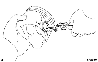
Using snap ring pliers, install a new snap ring on one side of the piston pin hole.
-
Gradually heat the piston to about 60°C (140°F).
-
Coat the piston pin with engine oil.
-
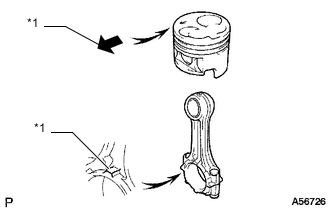
Text in Illustration *1 Front Mark Align the front marks of the piston and connecting rod, connect the connecting rod to the piston, and then push in the piston pin with your thumb.
-
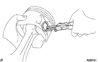
Check the fitting condition between the piston and piston pin. Try to move the piston back and forth on the piston pin.
-
Using snap ring pliers, install a new snap ring on the other side of the piston pin hole.
-
-
-
INSTALL PISTON RING SET
-
Install the piston rings.
-
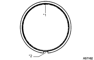
Text in Illustration *1 Coil Joint *2 Oil Ring Ends Install the coil and oil ring by hand.
Tech Tips
Make sure the end gap of the oil ring faces the opposite direction of the coil joint.
-
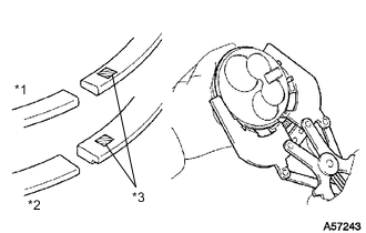
Text in Illustration *1 No. 1 *2 No. 2 *3 Code Mark Using a piston ring expander, install the No. 1 and No. 2 piston rings with the code mark facing upward.
Code Mark Item Code Mark No. 1 piston ring 1N No. 2 piston ring 2N -
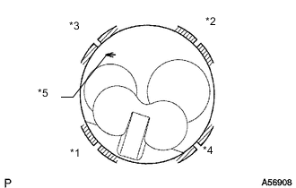
Text in Illustration *1 No. 1 Compression Ring *2 No. 2 Compression Ring *3 Oil Ring *4 Coil *5 Front Mark Position the piston rings so that the ring ends are as shown in the illustration.
Note
Do not align the ring ends.
-
-
-
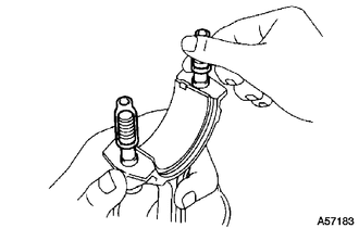
INSTALL CONNECTING ROD BEARING
-
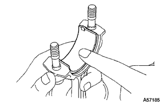
Align the bearing claw with the groove of the connecting rod or connecting rod cap.
-
Install the bearings to the connecting rod and connecting rod cap.
-
-
INSTALL CRANKSHAFT BEARING
Tech Tips
Upper bearings have an oil groove and oil hole; lower bearings do not.
-
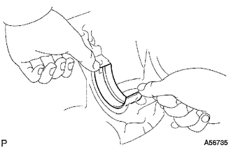
Align the bearing claw with the claw groove of the cylinder block, and push in the 5 upper bearings to install them.
-
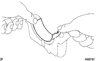
Align the bearing claw with the claw groove of the crankshaft bearing cap, and push in the 5 lower bearings to install them.
-
-
INSTALL CRANKSHAFT THRUST WASHER SET
-
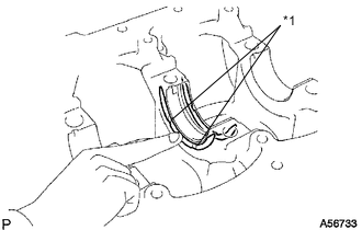
Text in Illustration *1 Oil Groove Install the 2 thrust washers to the No. 3 journal position of the cylinder block with the oil grooves facing outward.
-
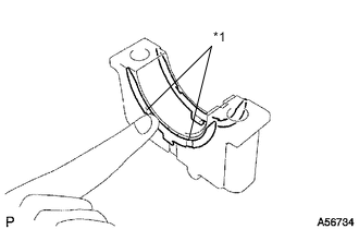
Text in Illustration *1 Oil Groove Install the 2 thrust washers to the No. 3 crankshaft bearing cap with the grooves facing outward.
-
-
INSTALL CRANKSHAFT
-
Place the crankshaft on the cylinder block.
-
Install the 5 crankshaft bearing caps in their proper locations.
-
Install the crankshaft bearing cap bolts.
-
Apply a light coat of the engine oil to the threads and under the bolt heads of the crankshaft bearing caps.
-
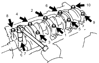
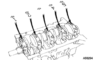
Install and uniformly tighten the 10 bolts of the crankshaft bearing caps, in several steps, in the sequence shown in the illustration.
- Torque:
- 105 N*m { 1071 kgf*cm, 77 ft.*lbf }
-
-
Check that the crankshaft turns smoothly.
-
Check the crankshaft thrust clearance Click here.
-
-
INSTALL PISTON AND CONNECTING ROD
-
Cover the connecting rod bolts with a short piece of hose to protect the crankshaft and cylinder bore from damage.
-
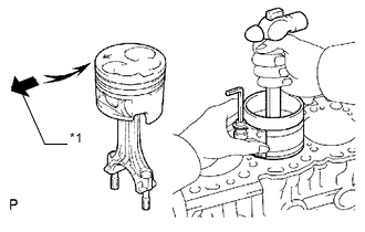
Text in Illustration *1 Front Mark Using a piston ring compressor, push the correctly numbered piston and connecting rod assembly into the cylinder with the front mark of the piston facing forward.
-
Place the connecting rod cap on the connecting rod.
-
Match each numbered connecting rod cap with the correct connecting rod.
-
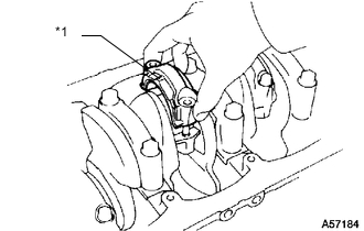
Text in Illustration *1 Front Mark Install the connection rod cap with the front mark facing forward.
-
-
Install the connecting rod cap nuts.
Note
If any connecting rod bolt is broken or deformed, replace it.
Tech Tips
The connecting rod cap nuts are tightened in 2 progressive steps.
-
Apply a light of engine oil to the threads and under the heads of the connecting rod cap nuts.
-
Step 1:
-
Install and alternately tighten the nuts of the connecting rod cap in several passes.
- Torque:
- 54 N*m { 551 kgf*cm, 40 ft.*lbf }
Tech Tips
If any one of the connecting rod cap nuts does not meet the torque specification, replace them.
-
-
Step 2:
-
Mark the front side of the connecting rod cap nuts with paint.
-
Tighten the connecting rod cap nuts 90° in the shown step 1.
-
-
Check that the painted marks are now at a 90° angle to the front.
-
Check that the crankshaft turns smoothly.
-
Check the connecting rod thrust clearance Click here.
-